sketch_dec18a.cpp:2:22: error: LCD4Bit.h: No such file or directory
sketch_dec18a:2: error: 'LCD4Bit' does not name a type
sketch_dec18a:3: error: 'LiquidCrystal' does not name a type
sketch_dec18a.cpp: In function 'void setup()':
sketch_dec18a:6: error: 'lcd' was not declared in this scope
These messages are confusing me...
sketch_dec18a.cpp:2:22: error: LCD4Bit.h: No such file or directory
suggests to me that the code cannot find the library, when it is saved here:
arduino21/libraries/LCD4Bit
You are invoking the LCD4Bit library and then are using LiquidCrystal commands.
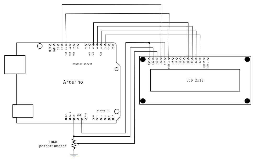
I suggest you start again and follow the tutorial at Arduino Tutorial - connecting a parallel LCD. Don't skip any steps especially this one "This means you've got the logic, backlight and contrast all worked out. Don't keep going unless you've got this figured out!" about halfway down, just before the Bus Wiring section.
well the lcd pin define looks ok for that pinout, i would say drop the 4-bit library and just go with the liquidcrystal library that comes with the Arduino IDE, it works.
a couple of things first, when you switch power on do you get a black bar across one line of the lcd but not the other line, if yes, the lcd's not initialised, if no black bar, check your contrast control pot
i would say drop the 4-bit library and just go with the liquidcrystal library that comes with the Arduino IDE
That's what I've done. At first, the program would not download onto the
board at all. I imported the LiquidCrystal library and ended up with two,
but the program did download:
Wiring looks ok but it's hard too tell, i usually use longer wires it's easier to trace, red, black power, blue data, green control, but thats just me,
Liquidcrystal Library should go here arduino-0021\libraries
having 2 includes of the same library may not be helping, if all else fails load the blink sketch with nothing connected and make sure your board is working.
Hard to see but are all the data lines 2,3,4,5 in the right positions
How far did you get before things did not work as depicted in the tutorial?
I got up to the step "Connect the Arduino up to power, you'll notice the
backlight lights up". I was not sure if my LCD had a backlight, so I carried
on. "Now turn on the Arduino, you'll see the backlight light up (if there is one), and you can also twist the pot to see the first line of rectangles appear." This did not work either (after I wired it up the other way).
I will try again soon with the LCD wired up the first way round.
The LCD interface uses 14 pins. Since your board has 16 pins it has a backlight. Did you look for pin number identification on both sides of the pc board? How about posting some nice clear photos of both sides of the board?
I suggest you disconnect everything and start again. Hook up only the backlight, the power, and the potentiometer (pins 1, 2, 3, 15, and 16. I really think that you should start by considering pin 1 to be near the edge of the board. Keep working at it until you see the black boxes. No amount of programming will help until you get this step working. You may possibly have one of the offbeat modules with the +5V and GND pins reversed . There is also a possibility that your LCD requires a negative voltage at pin 3.