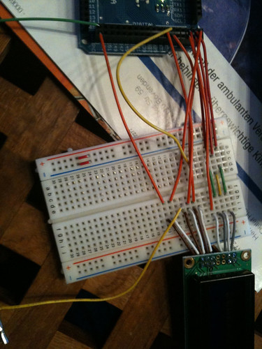
LCD broken or wrong code?

Hi guys,

i'm new on Arduino and got my Mega a few days ago. Same time I bought a 8x2 LCD Display with KS0066 Controller. Since there was talked about some problems using the Crystal lib for this LCD controller I decided to write my own method to use this LCD after I've had no luck with the LiquidCrystal lib.
But still i'm getting no screen output (Vee is set up with 900 Ohm resistor so contrast shouldn't be the problem). One line is black the other one brighter (same as when using the library).I've checked the wiring a lot of times but nothing seemed wrong .Here my code, which is build up considering the KS0066 datasheet (http: // pdf1.alldatasheet.com / datasheet-pdf/view/37318/SAMSUNG/ KS0066.html): (I always tried 4-Bit Mode)

//lcd defines
int E=30;
int RS=32;
int RW=31;
int DB4=25;
int DB5=24;
int DB6=23;
int DB7=22;

void setup() {
  lcdsetup();
  lcdsetcursor(0,0,0,0,0,0,0);
  lcdwrite0();
}

void loop() {
  // set the cursor to column 0, line 1
  // (note: line 1 is the second row, since counting begins with 0):
  //lcd.setCursor(0, 1);
  // print the number of seconds since reset:
  //lcd.print(millis()/1000);
}
void lcdsetup() {//connection routine
  pinMode(13,OUTPUT);
  pinMode(E,OUTPUT);
  pinMode(RS,OUTPUT);
  pinMode(RW,OUTPUT);
  pinMode(DB4,OUTPUT);
  pinMode(DB5,OUTPUT);
  pinMode(DB6,OUTPUT);
  pinMode(DB7,OUTPUT);
  delay(40);
  lcdbitsend(0,0,0,0,1,0);
  lcdbitsend(0,0,0,0,1,0);
  lcdbitsend(0,0,0,1,0,0);
  delay(4);
  lcdbitsend(0,0,0,0,0,0);
  lcdbitsend(0,0,1,1,1,1);
  delay(4);
  lcdbitsend(0,0,0,0,0,0);
  lcdbitsend(0,0,0,0,0,1);
  delay(4);
   lcdbitsend(0,0,0,0,0,0);
  lcdbitsend(0,0,0,1,1,1);
  delay(4);
}

void lcdbitsend(boolean lcdrs, boolean lcdrw,boolean lcddb7,boolean lcddb6,boolean lcddb5, boolean lcddb4){
  digitalWrite(E,HIGH);
  digitalWrite(RS,lcdrs);
  digitalWrite(RW,lcdrw);
  digitalWrite(DB7,lcddb7);
  digitalWrite(DB6,lcddb6);
  digitalWrite(DB5,lcddb5);
  digitalWrite(DB4,lcddb4);
  delay(2);
  digitalWrite(E,LOW);
  delay(10);
}

void lcdsetcursor(boolean d6, boolean d5, boolean d4, boolean d3, boolean d2 ,boolean d1, boolean d0){
  lcdbitsend(0,0,1,d6,d5,d4);
  lcdbitsend(0,0,d3,d2,d1,d0);
}

void lcdwrite0(){//write 0 character in DDRAM
  lcdbitsend(1,0,0,0,1,0);
  lcdbitsend(1,0,0,0,0,1);
}

This should print one '0' to the screen but it's doing nothing.

could it be that my NEW Lcd is broken or what is going wrong? No working with this, nothing different with the library. I'm in a lack of ideas.
Please help,

thanks a lot,

Nitro ::slight_smile:

Could you provide some more information about these statements:

But still i'm getting no screen output

This doesn't agree with the third statement below.

(Vee is set up with 900 Ohm resistor so contrast shouldn't be the problem).

How is it "set up"? You should be using a 10K potentiometer. Contrast may very well be the problem.

One line is black the other one brighter (same as when using the library)

What do you mean by "black". Do you mean a row of black boxes?
What do you mean by "brighter". Just about anything is brighter than black.
Which library.

Here's what you should do before you try your own code:
Use the LiquidCrystal tutorial as a guide http://arduino.cc/en/Tutorial/LiquidCrystal.

  1. Connect the power, contrast potentiometer and backlight (if equipped). Adjust the contrast until you get one row of black boxes and the other row blank.
    --> It is not worth trying anything else until you get this part working. <--

  2. Connect the rest of the pins. Don't forget to deal with R/W.

  3. Run the "Hello World" demo code under Arduino v0018.

If this doesn't work then post a photo showing your connections and the resulting display along with the corresponding code (all of it).

I'll check out your code later, after you add the comments.

Don

What do you mean by "black". Do you mean a row of black boxes?
What do you mean by "brighter". Just about anything is brighter than black.

  1. Connect the power, contrast potentiometer and backlight (if equipped). Adjust the contrast until you get one row of black boxes and the other row blank.
    --> It is not worth trying anything else until you get this part working. <--

This should be correct.
brigther means blank in this case but due to the contrast settings it's a Little bit darker.
I'll get a 10k poti Today and see if it solves the problem.

If this doesn't work then post a photo showing your connections and the resulting display along with the corresponding code (all of it).

Yes, it doesn't work after following this steps. I'll post the wiring: here it is: djnitro | Flickr
And the datasheet: http://www.produktinfo.conrad.com/datenblaetter/175000-199999/181647-da-01-en-LCD_MOD_STN_BLAU_NEG_LED_WEISS_8_X_2.pdf

Which library.

LiquidCrystal.

Here's what you should do before you try your own code:
Use the LiquidCrystal tutorial as a guide http://arduino.cc/en/Tutorial/LiquidCrystal.

already did that but got no results

thanks for your help,

Nitro.

I'll get a 10k poti Today and see if it solves the problem.

That is a good idea.

Your display should be blank with the pot at one end of it's range and you should have a really dark row of blocks on the top line of the display with the pot at the other end.

If you look at your datasheet you will see that the typical LC driving voltage is 4.4 volts less than Vcc which would put it at about 0.6 volts. This means that the correct setting of the pot will be pretty close to the end that gave the row of dark blocks.

Don

Okay I took a poti from school when i'm at home i'll see what's the result.

Comment: Okay, i've got the poti and nothing is better. As you say i've one blank and one black line when resistor is turned on to one side and on the other two black lines but no output with my code or with the liquid chrystal lib

Okay the result screen is now on flickr:
Imgur

I have this result with my own code and this hello world code:

The code was:

/*
  LiquidCrystal Library - Hello World
 
 Demonstrates the use a 16x2 LCD display.  The LiquidCrystal
 library works with all LCD displays that are compatible with the 
 Hitachi HD44780 driver. There are many of them out there, and you
 can usually tell them by the 16-pin interface.
 
 This sketch prints "Hello World!" to the LCD
 and shows the time.
 
  The circuit:
 * LCD RS pin to digital pin 12
 * LCD Enable pin to digital pin 11
 * LCD D4 pin to digital pin 5
 * LCD D5 pin to digital pin 4
 * LCD D6 pin to digital pin 3
 * LCD D7 pin to digital pin 2
 * 10K resistor:
 * ends to +5V and ground
 * wiper to LCD VO pin (pin 3)
 
 Library originally added 18 Apr 2008
 by David A. Mellis
 library modified 5 Jul 2009
 by Limor Fried (http://www.ladyada.net)
 example added 9 Jul 2009
 by Tom Igoe
 modified 25 July 2009
 by David A. Mellis
 
 
 http://www.arduino.cc/en/Tutorial/LiquidCrystal
 */

// include the library code:
#include <LiquidCrystal.h>

// initialize the library with the numbers of the interface pins
LiquidCrystal lcd(32, 30, 25, 24, 23, 22);

void setup() {
  // set up the LCD's number of rows and columns: 
  lcd.begin(16, 1);
  // Print a message to the LCD.
  lcd.print("hello, world!");
}

void loop() {
  // set the cursor to column 0, line 1
  // (note: line 1 is the second row, since counting begins with 0):
  //lcd.setCursor(0, 1);
  // print the number of seconds since reset:
  //lcd.print(millis()/1000);
}

OK - The third photo shows that the contrast is acceptable. You may want to tinker with it after you get the rest working.

Now you have to get your connections cleaned up and organized.
(1) Remove all the wires (ouch).
(2) Arrange the 14 connections between your LCD module and the breadboard so that they are in a single row on the breadboard, just as if you had plugged in one of the modules that has all 14 pins in a single row.
(3) Reconnect the power and the contrast potentiometer and make sure you see the blocks again.
(4) Connect R/W to ground (you did do that before, didn't you?).
(5) Connect the other six lines, using different colored wires if possible.
(6) Enjoy your Hello World display.

Don

Thanks, it's working now.

I just added all the wires and now everything's fine!