Hi,
i'm building a soil moisture sensor using Raspberry Pico, Capacitive sensor, and OLED LCD Display. The programming works when I click upload the LCD display works but it turns off right away when I touch the capacitive sensor or grab it to to put it to the soil. I think it could be the system of the red wire (3.3v) and it could be the wiring part not the programming.
Great you followed the guidelines for posting code. Next we need an annotated schematic showing exactly how you have wired it. Be sure to show power, ground and all power sources. Post links to your hardware items such as the sensors, processors etc.
Yes, I do have a capacitive sensor V2.0 and it is wired to the pico board. I mention the sensor in my raspberry pico code which I used it to monitor the dry and wet reading it but not in this code.
In what possible way is this a schematic?
Are you incapable of drawing one or are you just being disrespectful?
Unless you can cooperate with us, how do yo expect us to be able to help you?
Is it your sensors that you are calling Capacitive sensors?
If you cannot answer my questions then i cannot answer yours. It is simple logic I am not there nor can I see what you have and I am not clairvoyant so???
Sorry for the inconvenience i'm new to programming and thats why I wasn't able to do schematic yesterday I wasn't trying to disrespect any of you, I understand the value of your times.
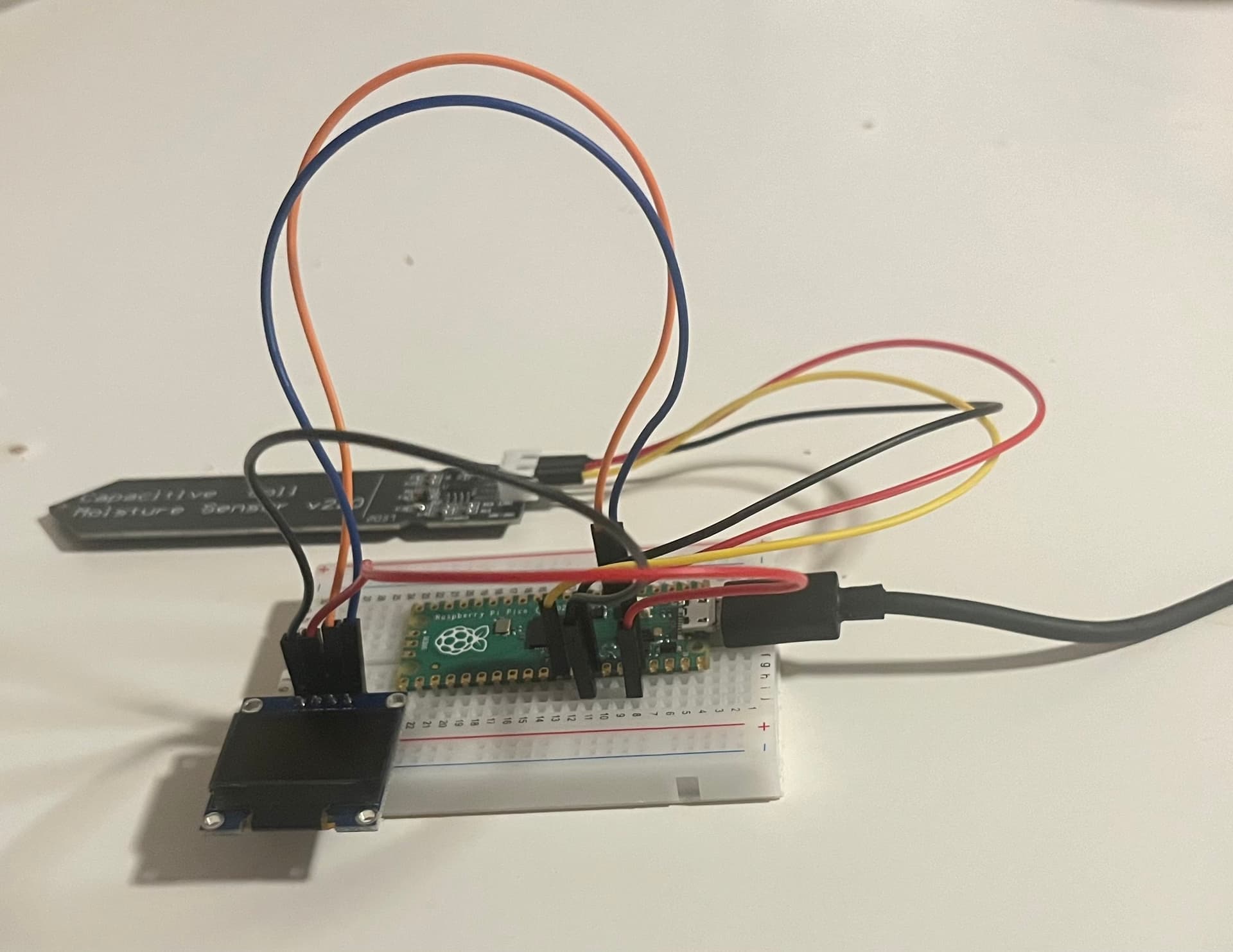
Here it is, I know its a bit mess so feel free to ask for any more info.
Also the LCD display itself isn't turning on at all today even if I change the delay in the code from 100 to 500 and to 1000. The past few days it would turn on after a few times but not today.
Then your wiring has gone bad on that solderless bread board. They are prone to doing this. Remove each connector in turn and re insert it. Until your display works again.
You have absoloutly no decoupling capacitors on anything and no pull up resistors on the I2C lines.
Put a 3K3 ( to 1K8) pull up resistor from each of the I2C lines (SDA and SCL) and include a 0.1uF ceramic capacitor between a digital ground and 3V3. Do not wire everything to the analog ground pin, for digital circuits you need a digital ground.
Now, please supply a link to your soil sensor. I can't tell you what to do exactly until I have read the specification. Particularly should it be powered by 3V3 or 5V and what sort of signal it outputs in terms of impedance. This will sort out what signal conditioning you need to use to prevent your "touching" the sensor causing a problem.
Finally please tell us what sort of frame work you are using to program this in an Arduino environment.
for my project and the code for raspberry worked however not for the LCD display as I was receiving error because one of the required hardware doesn’t support the program I was using. I was told by someone in this community to go for an alternative which I did and I changed the code for majority of it.