Hello everybody Im new to this forum.I'm a pathologist working on a research project. As part of this project need to blink a 5m strip of LED light at 4O Hz using the arduino board as the controller. Also I need to know how to output the signal to be of sufficient intensity so as power the strip. All help is welcome and will be duly acknowledged.
This is the specs of the LED strip.
Ir InfraRed 850nm 940nm Fita led strip light DC 12V SMD3528 60leds/m.
We are dying to help you.
tone(LEDpin, 40); //send a tone of 40Hz to the LED pin.
What LED strip do you have? (need a link)
A MOSFET transistor can easily drive a simple LED.
Hi larryd,
Thanks for your eagerness to help. I'm sending you the link of the led strip. Hope you can take it further.
https://m.aliexpress.com/item/32843638283.html?trace=wwwdetail2mobilesitedetail&spider=y&productId=32843638283&productSubject=Ir-InfraRed-850nm-940nm-Fita-led-strip-light-DC-12V-SMD3528-60leds-m-IR-LED-Tape


Thanks larryd. But I guess Ill have to take some professional help as I have no idea what these circuits mean. On the other hand if you could guide me on what components I have to procure maybe I could give it a try. Thanks anyway for all the help.
If you don't have time to learn to read schematics or solder your own board from individual components, you could use one of these. It is a ready-made equivalent of the above circuit. You will also need a 12V power supply and some jumper wires.
This is in effect three times what Larry drew, you just need one of them:-
Hi PaulRB Just wanted to know if this thing would be do the job. I already have the power supply and will be ordering the cables as well. Thanks
veegee:
Just wanted to know if this thing would be do the job.
Looks identical to the one I gave you the link to.
Next question: do you really need an Arduino for this? Perhaps you could use one of these signal generators instead.
Serial interface and all? PWM? Makes you wonder what's in it. ![]()
Remarkably cheap!
Just ordered one to check it out. Give it a month. ![]()
The thing that worries me about the OP's LED strip is the description that says:-
Ir InfraRed 850nm 940nm Fita led strip light DC 12V SMD3528 60leds/m IR LED Tape
Now IR LEDs are either 850nm or 940nm not both at the same time. It could mean that the strip alternates between a 850nm LED and a 940nm LED. But what I guess is that the seller hasn't got a clue about what he is selling.
As this is for research then you must check exactly what you have.
Grumpy Mike, Just received the package yesterday. It says LED color 940nm. So no confusion there.
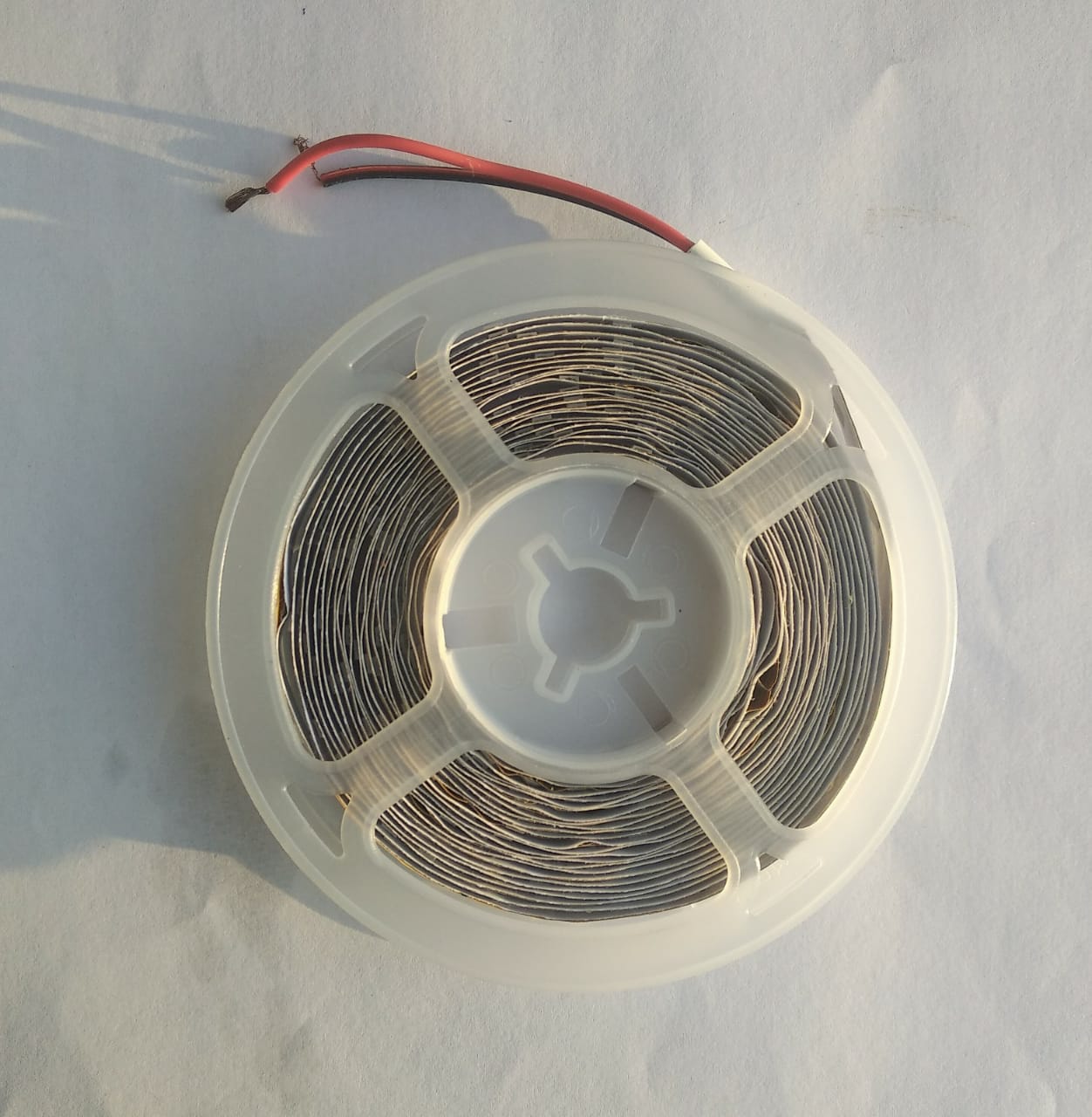
Hello everyone. Back again after a long break. Wish to re-start the project which is stalled. This is the stuff that I have. Want to flash the Red LED's at 40 Hz. Knowledge of electronics is zero. May be able to program the board though. Basic issue here is what gets connected...at what terminal. Circuit diagrams are a no-no. I wouldnt be able to follow them. If you could just point out on the attached pictures it would be of great help. Thanks again
1.doc (122 KB)
2.doc (141 KB)
3.doc (158 KB)
4.doc (86 KB)
Can't open those attachments on my phone or tablet. What are they? Can you post as pdf or jpg?
I mean, really!
Do you not know what an "image" is? Does your camera take "doc" files?


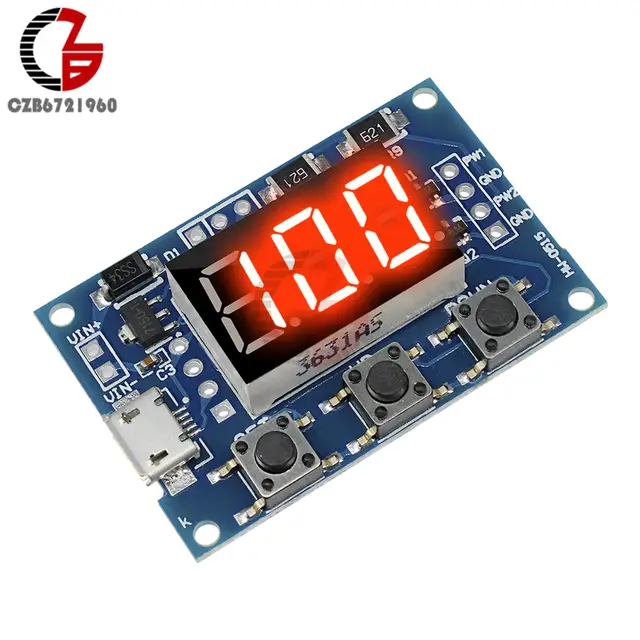
Well, that's a start but those pin headers are useless - you cannot connect anything to the short end, neither the socket headers on the bogus "UNO" nor the "Dupont" wires with female connectors. They just will not work (or if you think they do, you will get a nasty surprise when they fall apart). ![]()
You need male to female Dupont" wires to connect the FET module to the bogus "UNO" and some plain "figure 8" wire to connect the power supply to the FET module. The LED strip has enough wire to connect to the FET module but it would be nice to get someone who can solder, to strip and "tin" the ends of each of the power wires for you so they connect more cleanly in the screw connectors. ![]()
Circuit diagrams are a no-no.
It is like my wife many years ago, she learned how to ask to directions for locations in German, but in practice this was useless because she couldn't understand the answers she got.
Paul__B:
Serial interface and all? PWM? Makes you wonder what's in it.
OK, so I did receive this a few months back (more than I can say for half the stuff I have ordered from greater Wuhan since Covid-19) but have not done anything with it. I may go excavate it and check it out having been thus prompted.
I could couple it with one of these (which I bought well before the plague and its effect on mailing prices and reliability and containers falling off ships):

Yes. I know it has the wrong FET but it will be OK for less than an Amp.
The first step is to start understanding circuit diagrams. Electronics is not Lego and if you want to achieve things, circuit diagram understanding is essential.