I am new to this, so please have patience on me.
I assembled project #1 to test some LEDs, to see if I had any burned down. And this worked fine.
I then decided to add a potentiometer to see test varying brightness. This also worked fine but only up to a point. If turned the pot up too much, the LEDs would burn. I placed the resistor right after the middle pot pin and before the LED anode lead. Confused, I then placing the resistor after the cathode, before ground - it also failed, and it burned when the knob was too up. The resistor was the same as the one used in project #1, so LED burning is likely to be due to the arrangement, but I don't get it what I did wrong.
You will need to know the Max Forward voltage and the forward current of the LED, the supply voltage that you are driving the led with and then you can calculate what size resistor you will need to achieve said maximum forward voltage.
Search google for "LED Calculator" and take your pick
LEDs are current controlled devices. Using a potentiometer in your LED circuit controls the current though the LED. The problem is when the resistance of the potentiometer decreases so much (by turning the knob) that it causes excess current through the LED, which will cause it to burn.
What you should've done is place a fixed resistance current limiting resistor (220ohms or so) in series with your LED and potentiometer. That way when the potentiometer's resistance is too low, the fixed resistor keeps your LED from burning.
Are you even using an Arduino? Or is this a potentiometer in series with an LED and no microcontroller involvement at all other than maybe power source?
Guys, many thanks for all your suggestions and interest.
I see I did not explain myself very well. When I mentioned Project #1, I was referring to project #1 of the Genuino Start Kit which is a simple LED+Resistor circuit (sorry, my bad should have made that more clear). So yes, I was using Arduino to power the circuit, however I wanted to make to whole thing analog and purposefully wanted to avoid using any code.
So, I now try to make things a bit more transparent by providing photos.
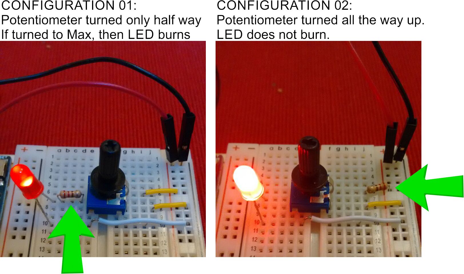
I attach here image with two configurations of the circuit.
In configuration 01, which is the one I attempted to describe earlier, the 220 Ohm is placed in front of the middle pin of the potentiometer, and before the anode lead of the LED. In this configuration I cannot turn the potentiometer all the way up without burning the LEDs I have.
In configuration 02, which I tried just now, I placed the 220 Ohm resistor before the potentiometer, therefore limiting the current at the potentiometer. In this configuration I can perfectly turn the knob all the way up without burning it.
Hence my perplexity:
Without the potentiometer, the circuit works fine and the LED does not burn
With the potentiometer being limited by a resistor such as in configuration 02, the LED also does not burn.
Inf instead the resistor is moved to after the potentiometer, then "Huston, we have a problem".
My very poor knowledge of electronic circuits would tell me that both configuration 01 and 02 are equivalent, as long as the current is limited before it reaches the LED that is what it matters, if a potentiometer is placed before or after the resistor it should not matter. But this is more striking that the presence of the potentiometer can cause the LED to burn. Does this makes sense? If so, please explain.
Many thanks to everybody, please drop in your thoughts!!
In the left hand picture, the LED anode and resistor leads are all connected together. The resistor is thus shorted out. Turning the pot all the way up thus applies 5V (or whatever your power source is) to the LED with no current limiting.
Move the anode and one resistor leg into the next set of holes up, row 5 or 6, so there is a series connection from wiper to resistor to anode.