So I'm learning about arduino with the help of the "Getting started with arduino" book (2nd edition) by Massimo Banzi (Yay arduino dude!). I am working on an example involving an LED and a pushbutton with the pushbutton controling the brightness of the LED depending on how long it is pressed. The longer it's pressed, the brighter it gets. If it is pressed quickly the LED turns off.
At least that's how it's supposed to work.
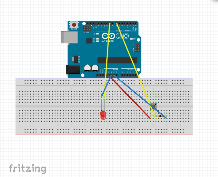
I've wired the circuit as shown below in the fritzing image, and used the code posted below. It is straight from the book, word for word, but I'm having weird results. Whenever I upload the code the LED begins blinking, fading from full brightness to off, then back to full. Regardless of me pressing the button or not, as if the button made no difference or wasn't even involved in the whole thing. I'm unsure at this point if my problem is in the wiring or the code (my guess would be code....?). Any ideas? I've tried looking up problems with the example or instructions and can't seem to find anything so it must be something I'm missing... I've triple checked my code and it is same as the book.
const int LED = 9; // LED pin 9
const int BUTTON = 7;//Button pin 7
int val =0; //value variable
int old_val = 0;
int state = 0; //used to keep track of button
int brightness = 128; // value for the brightness of the led
unsigned long starttime = 0; // to keep track of how long the button has
                             //been pressed

void setup(){
  pinMode (LED, OUTPUT);
  pinMode (BUTTON, INPUT); //Setting input/output pins
}

void loop(){
  val = digitalRead (BUTTON);
  if((val = HIGH) && (old_val == LOW)){ //if the button was pressed
    state = 1-state;
    starttime = millis();
    delay (10);
  }

  if ((val==HIGH) && (old_val== HIGH)){ //if button is being held down
    if (state ==1 && (millis()-starttime)>500){
      brightness++;
      delay(10);
      if(brightness>255){
        brightness=0; //write brightness up to 255 if going over turn off
      }
    }
  }
  old_val = val;
  if (state ==1){ //rewrite the brightness value based on time pressed
    analogWrite (LED,brightness);
  }else{
    analogWrite(LED,0);//if state is 0 then turn LED off
  }
  if(state==0){
    analogWrite(LED,0);
  }
}
Thanks for the feedback Grumpy_Mike. I actually ended up removing the resistor since the LED wouldn't turn on with any kind of resistor. Book suggested a 270ohm but whenever it was there LED would't work. I tried with down to a 50ohm actually have that wired in there. I've checked the wiring and it matches! So good to hear at least that looks good... Here's the updated image of the wiring.
I actually ended up removing the resistor since the LED wouldn't turn on with any kind of resistor.
That is wrong.
If the LED will not turn on with a 270R resistor then it sounds like your solderless bread board is shot or not making proper connection. Rebuild the circuit with the resistor using different holes, that is move it along the breadboard five holes or so. Then you do not use the same tracks.
Sounds like you have the same problem with your switch.
This is why I hate solderless bread board, it gives you extra troubles.
Well I tried a smaller resistor value on the same holes on the breadboard and the LED worked fine. The pushbutton I moved to a different place and seems to have not changed anything.
I left the wiring the same and setup the pushbutton LED example (on and off when button is held) and it worked just fine so it seems the button and LED, alongside with their respective position on the breadboard work fine....
Whenever I upload the code on the above sketch though the LED just fades in an out still, regardless of the button presses (supposed to turn it on and off at a quick press and change brightness when held)
Well I tried a smaller resistor value on the same holes on the breadboard and the LED worked fine.
So did you put the original 220R back? Was the lead of this resistor tarnished in some way?
Basically thousands of people have done this tutorial, and the fact that you can not get it to work means that you are doing something wrong. What we have to do is to find out what. You are offering no more information than the simple, "yes I did that but it still didn't work".
How about posting a photograph ( not more than 1000 pixels ) of your set up so we can see if we can spot your error.
Sounds good, I got it to work with a 50ohm resistor but even the 220ohm wouldn't do it making it past a very faint glow. (tried different LEDs). Here'a link to the setup image I was able to take with my phone. Hope it helps see what's going on.
FINALLY. I rewrote my code and rebuilt the circuit the exact same way with a 150ohm resistor and it worked flawlessly. No idea yet as to what the error was... (code maybe? Still copied off same part of book...)
Regardless I appreciate the help Mike. Good karma headed your way
I came across this a short time ago, read the second answer.
Sometimes those bread boards have a break in the middle of the power supply traces. I notice you have got some home made colored lines. Have you checked the continuity from one end to the next. That might explain your symptoms of the LED working but the switch not.