I plan to make arduino 2560 turn itself off at a given time. Plus I want have the following features:
The arduino is powered by batteries (2V~3V). So I implemented a step-up DC-DC circuit.
I want to have a single press button on-off switch.
So I think I need to implement the missing auto turn off part by leading a digital output of the arduino to the dc dc enable pin. Is there any better idea?
The circuit below uses a push button to turn on the power, but after that the button becomes an input which the Arduino can read and then shut itself down. However, the circuit may not work with battery voltages as low as 2V. There has to be enough difference between the gate and the source to turn on the mosfet. The regulator isn't shown, but would be between the mosfet and the Arduino.
One thing to be careful about if you connect a GPIO pin to the enable pin of the boost regulator. When the processor shuts down, it will no longer be able to assert that signal, and the regulator may turn on again, which will power up the Arduino again, etc.
I found some AO3401a, which said the gate threshold voltage is -0.5(min) -0.8(typical) and -1.5(max). Doest it mean by using this one, the battery voltage can be as low as 1.5V?
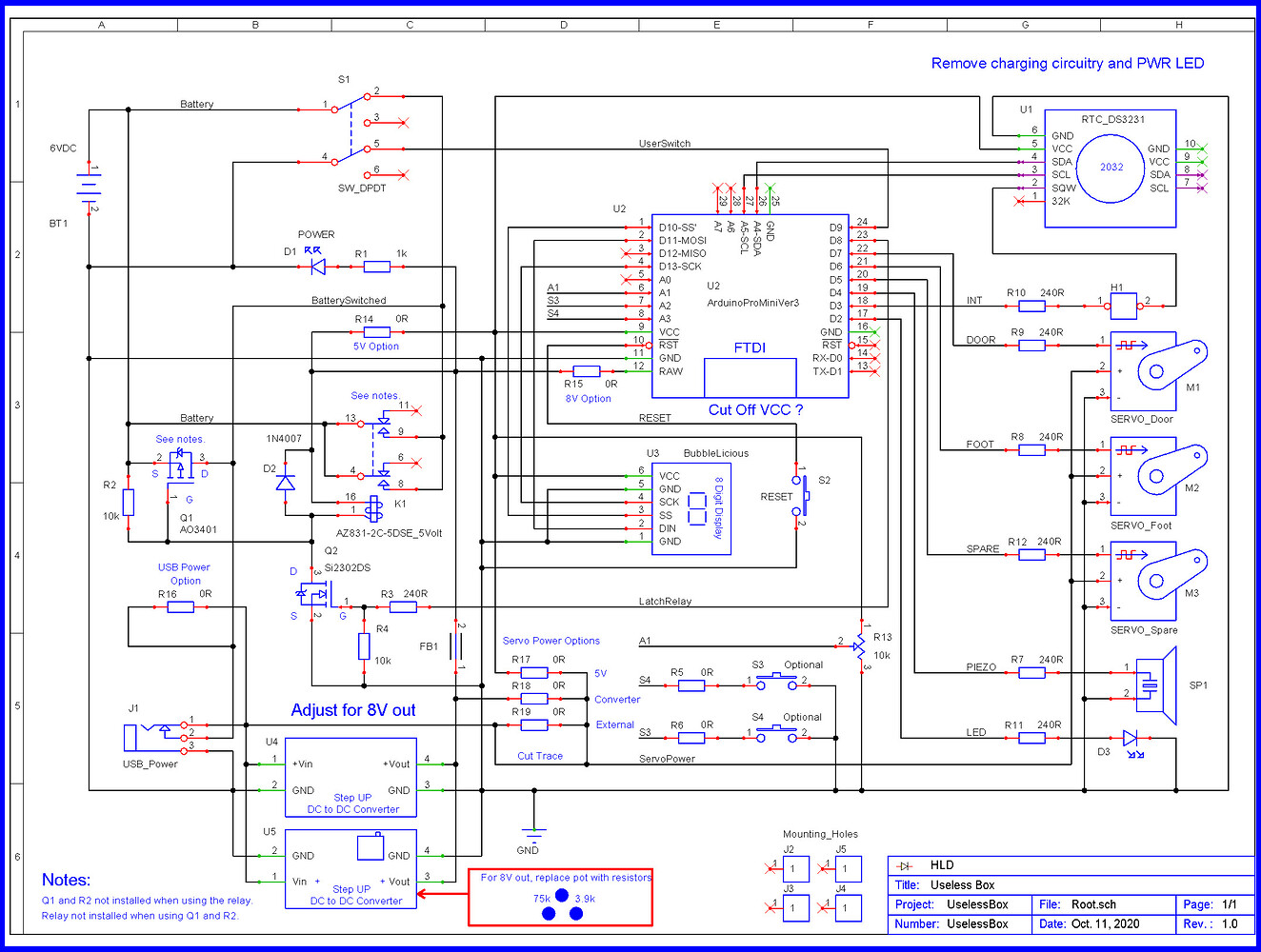
I think I understand the work principle of this shematic The Q1 is the main current path to the DC DC converter, and the Q2 is in charge of turning Q1 on and off. Initially, S1 bypassed Q1 and turned on Q2, so that Q2 turns on Q1 even if S1 is open afterwards. And does S1 also turn off Q1? I don't quiet get that part.
In some circuit, one has to press and hold the power button for a while in order to turn on/off it. So I think maybe one should add a cap to the push button of this cirtuit? Or maybe that requires a whole diffferent circuit?
I’ve used these as low 1.8v, it may work with 1.5v.
Q2 (under software control) keeps Q1 turned ON after S1 starts the Power ON cycle.
When software sends a LOW to Q1 the power is disconnected from the converter.
In this particular circuit, S1 will not turn OFF to power.
Oh, I think the Vbattery must >= VgsQ1threshold+VdsQ2 in order to have this guy work. So if I want the Vbattery to be as low as 2V, the VdsQ2 must be smaller or equal to 2-1.5=0.5V. I am not sure if this is ok, cause the Q2 required higher Vgs to turn on and in this case, the DC DC will only give 3.3V to the arduino. Do you think it is a better idea to use a triode instead of FET as Q2?
Do you think I should apply some extra circuit to avoid the MCU turn on and off multiple time issue mentioned by ShermanP?
The problem I mentioned was related to the idea of driving the boost converter's EN pin from the Arduino. But you aren't doing that in LarryD's circuit in post #5. You're powering down the converter instead.
I have one quibble with LarryD's circuit which doesn't mean anything here but might in another design. The gate pulldown resistor of the lower N-channel mosfet should be placed to the right of the gate series resistor. That would eliminate the divider that results from the existing placement. I said it was a quibble, didn't I?
While as long as the ratio of resistors is high, it makes little difference to the actual drive voltage to the FET, it is a matter of understanding the engineering principles.
It is not a matter of "needing to pull down the FET gate". The reason you have a pull-down resistor is that until (and unless) the Arduino code initialises, all its outputs are floating and the gate voltage would be otherwise undefined. The threefold consequences of this are that the device controlled by the FET may be prematurely activated to damaging effect, that if the FET is only partially switched on, it may overheat from the load current (hardly a problem here), and that in this particular case, the system will switch on spontaneously.
Actually, that last case is not true anyway as with no power to Vcc, the protection diodes in the Arduino chip do definitely pull the I/O pins down to 0.6 V or less and the pulldown is actually unnecessary.
So the pull-down resistor is there to address a problem generated by the Arduino, so should be connected to directly pull down the Arduino pin itself, not the FET gate.
Also where the pull-down resistor is necessary due to the driver circuit not actually having a totem pole output, such as where it is being driven only by a PNP transistor, the pulldown needs to be a much lower value to provide sufficiently fast switching.
Thanks Larry, is there a way to improve this circuit, so that the s1 will be able to turn off the power, either by software or by hardware(prefered). I found it is hard to turn off the power at this point, after I had built severl pcbs....
It is a good idea, but would be a little bit old school... You know space X has made a big progress recently, ... we really need to catch up. And Cook will fire me if I implement this in our current project--iphone XO.
I mean one push button controlls both on and off is quiet common today, like my laptop/desktop.
Do you think I need an extra input for the MCU, like ShermanP's design in #4?
I followed your design, and use an ao3401a as the p channel fet. But when the circuit is in off state, the current is consumed by the whole ciruit (including dc-dc regulator and the arduino) is still ~9mAh. I don't have a meter with me to measure the current in the different circuit branches. I wonder if it is due to the fet (ao3401). I would like to try to add a resistor between the fet and the transistor to upper the G voltage when the circuit is off. Or, maybe the Rsd of this ao3401 is low anyway even when the fet is "off", then I need a differnet fet.