lg air conditioner decoding

hello everyone!

i just try to get a signal from my lg air conditioner, i get this :

Received: 

OFF 	ON
17148 usec, 8340 usec
4140 usec, 560 usec
1580 usec, 560 usec
500 usec, 580 usec
500 usec, 560 usec
520 usec, 560 usec
1560 usec, 580 usec
500 usec, 560 usec
500 usec, 580 usec
500 usec, 580 usec
480 usec, 580 usec
500 usec, 560 usec
520 usec, 560 usec
500 usec, 560 usec
520 usec, 560 usec
1580 usec, 560 usec
500 usec, 580 usec
500 usec, 560 usec
1580 usec, 560 usec
500 usec, 560 usec
1580 usec, 560 usec
1580 usec, 580 usec
500 usec, 560 usec
500 usec, 560 usec
1580 usec, 580 usec
500 usec, 560 usec
500 usec, 580 usec
500 usec, 560 usec
520 usec, 560 usec
1560 usec, 580 usec
int IRsignal[] = {
// ON, OFF (in 10's of microseconds)
	834, 414,
	56, 158,
	56, 50,
	58, 50,
	56, 52,
	56, 156,
	58, 50,
	56, 50,
	58, 50,
	58, 48,
	58, 50,
	56, 52,
	56, 50,
	56, 52,
	56, 158,
	56, 50,
	58, 50,
	56, 158,
	56, 50,
	56, 158,
	56, 158,
	58, 50,
	56, 50,
	56, 158,
	58, 50,
	56, 50,
	58, 50,
	56, 52,
	56, 156,
	58, 0};

how i get the original singal for sent to air conditioner?

tnx all!

this my emitter and receiver :
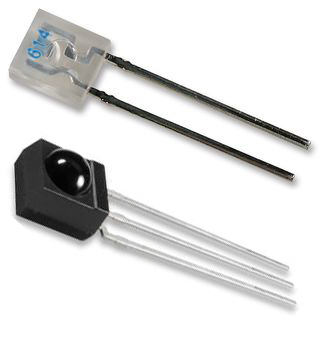
![](http://i.ebayimg.com/t/IR-emitter-receiver-Universal-Remote-36KHZ-Arduino-/00/s/MzQwWDMyMA==/$(KGrHqJ,!joE9UbgeycIBPntV1BPsw~~60_1.JPG)

datasheet : http://www.arduinodiy.co.uk/ebayimages/ebaycontent/IrReceiver30492.pdf

up?

how did you collect the data - was it from remote - do you have a sketch running on a arduino with a led reciever connected

and this is the code

#define IRpin_PIN PIND
#define IRpin 2
// for MEGA use these!
//#define IRpin_PIN PINE
//#define IRpin 4
 
// the maximum pulse we'll listen for - 65 milliseconds is a long time
#define MAXPULSE 65000
 
// what our timing resolution should be, larger is better
// as its more 'precise' - but too large and you wont get
// accurate timing
#define RESOLUTION 20
 
// we will store up to 100 pulse pairs (this is -a lot-)
uint16_t pulses[100][2]; // pair is high and low pulse
uint8_t currentpulse = 0; // index for pulses we're storing
 
void setup(void) {
  Serial.begin(9600);
  Serial.println("Ready to decode IR!");
}
 
void loop(void) {
  uint16_t highpulse, lowpulse; // temporary storage timing
  highpulse = lowpulse = 0; // start out with no pulse length
  
  
// while (digitalRead(IRpin)) { // this is too slow!
    while (IRpin_PIN & (1 << IRpin)) {
     // pin is still HIGH
 
     // count off another few microseconds
     highpulse++;
     delayMicroseconds(RESOLUTION);
 
     // If the pulse is too long, we 'timed out' - either nothing
     // was received or the code is finished, so print what
     // we've grabbed so far, and then reset
     if ((highpulse >= MAXPULSE) && (currentpulse != 0)) {
       printpulses();
       currentpulse=0;
       return;
     }
  }
  // we didn't time out so lets stash the reading
  pulses[currentpulse][0] = highpulse;
  
  // same as above
  while (! (IRpin_PIN & _BV(IRpin))) {
     // pin is still LOW
     lowpulse++;
     delayMicroseconds(RESOLUTION);
     if ((lowpulse >= MAXPULSE) && (currentpulse != 0)) {
       printpulses();
       currentpulse=0;
       return;
     }
  }
  pulses[currentpulse][1] = lowpulse;
 
  // we read one high-low pulse successfully, continue!
  currentpulse++;
}
 
void printpulses(void) {
  Serial.println("\n\r\n\rReceived: \n\rOFF \tON");
  for (uint8_t i = 0; i < currentpulse; i++) {
    Serial.print(pulses[i][0] * RESOLUTION, DEC);
    Serial.print(" usec, ");
    Serial.print(pulses[i][1] * RESOLUTION, DEC);
    Serial.println(" usec");
  }
  
  // print it in a 'array' format
  Serial.println("int IRsignal[] = {");
  Serial.println("// ON, OFF (in 10's of microseconds)");
  for (uint8_t i = 0; i < currentpulse-1; i++) {
    Serial.print("\t"); // tab
    Serial.print(pulses[i][1] * RESOLUTION / 10, DEC);
    Serial.print(", ");
    Serial.print(pulses[i+1][0] * RESOLUTION / 10, DEC);
    Serial.print(",");
  }
  Serial.print("\t"); // tab
  Serial.print(pulses[currentpulse-1][1] * RESOLUTION / 10, DEC);
  Serial.print(", 0};");
}

To get the TV-B-Gone working they had to sample IR signals and create profiles for the commands. This should be very similar to what you are trying to do.
http://www.ladyada.net/make/tvbgone/design.html

Don't know if this will assist with your original question but following is a published method to read IR data and display it using gnuplots

/* Infrared receiver modules
Unfortunately there are almost as many infrared protocols as there are devices that use them.
If your goal is to control something connected to the arduino with a standard remote control then the
easiest way is to purchase a programable remote. Configure it to use a Sony TV protocol and use the code
posted at http://www.arduino.cc/cgi-bin/yabb2/YaBB.pl?num=1176098434 by Paul Malmsten
However, if you want to integrate the arduino into an existing infrared remote system, then you need
to identify the protocol in use. The first step is to capture that protocol.
If you have access to a DSO (even a Parallax Optascope or USB Stingray will work) then it's easy.
However, if you're not so equipped I've developed an arduino sketch that will allow a standard 3-pin IR receiver
module to be connected to the arduino and the signal changes to be captured with a 4uS resolution.
/
/

  • File....... IRanalyzer.pde
  • Purpose.... Records up to 128 signal changes
  • Author..... Walter Anderson
  • E-mail..... wandrson@walteranderson.us
  • Started.... 18 May 2007
  • Updated.... 18 May 2007

*/
#include <avr/interrupt.h>
#include <avr/io.h>

#define TIMER_RESET TCNT1 = 0
#define SAMPLE_SIZE 64

int IRpin = 2;
unsigned int TimerValue[SAMPLE_SIZE];
char direction[SAMPLE_SIZE];
byte change_count;
long time;

void setup() {
Serial.begin(115200);
Serial.println("Analyze IR Remote");
TCCR1A = 0x00; // COM1A1=0, COM1A0=0 => Disconnect Pin OC1 from Timer/Counter 1 -- PWM11=0,PWM10=0 => PWM Operation disabled
// ICNC1=0 => Capture Noise Canceler disabled -- ICES1=0 => Input Capture Edge Select (not used) -- CTC1=0 => Clear Timer/Counter 1 on Compare/Match
// CS12=0 CS11=1 CS10=1 => Set prescaler to clock/64
TCCR1B = 0x03; // 16MHz clock with prescaler means TCNT1 increments every 4uS
// ICIE1=0 => Timer/Counter 1, Input Capture Interrupt Enable -- OCIE1A=0 => Output Compare A Match Interrupt Enable -- OCIE1B=0 => Output Compare B Match Interrupt Enable
// TOIE1=0 => Timer 1 Overflow Interrupt Enable
TIMSK1 = 0x00;
pinMode(IRpin, INPUT);
}

void loop()
{
Serial.println("Waiting...");
change_count = 0;
while(digitalRead(IRpin) == HIGH) {}
TIMER_RESET;
TimerValue[change_count] = TCNT1;
direction[change_count++] = '0';
while (change_count < SAMPLE_SIZE) {
if (direction[change_count-1] == '0') {
while(digitalRead(IRpin) == LOW) {}
TimerValue[change_count] = TCNT1;
direction[change_count++] = '1';
} else {
while(digitalRead(IRpin) == HIGH) {}
TimerValue[change_count] = TCNT1;
direction[change_count++] = '0';
}
}
Serial.println("Bit stream detected!");
change_count = 0;
time = (long) TimerValue[change_count] * 4;
Serial.print(time);
Serial.print("\t");
Serial.println(direction[change_count++]);
while (change_count < SAMPLE_SIZE) {
time = (long) TimerValue[change_count] * 4;
Serial.print(time);
Serial.print("\t");
Serial.println(direction[change_count-1]);
Serial.print(time);
Serial.print("\t");
Serial.println(direction[change_count++]);
}
Serial.println("Bit stream end!");
delay(2000);
}

/*
The data displayed in the Serial Monitor can be cut and pasted into a data file
and displayed using software such as gnuplot (which is available for most platforms)
using the command plot '\pathname\datafilename.dat' using 1:2 with lines
An example output from my cable remote using this sketch and gnuplot
is shown in the attached pdf document.
*/