At the moment I am trying to build a remote controlled Lego Car. I use an Arduino Uno with the Adafruit Motor Shield v.1 and an Arduino Nano with a two-achsis-joystick as a remote. The Y-achsis of the Joystick should steer the car and the other achsis should control the motor speed.
I included the ServoTimer2 library, because the Servo.h and the VirtualWire library are not working together very well.
The transfer from the remote is working (serial monitor is giving the right feedback), but if I attach the servomotor, the DC-Motor will not run. Without the code “servo1.attach(ServoPin)” the Lego-motor can be controlled with the joystick.
At first I did not use the 433MHz RF transmitter/receiver an attached the joystick directly to the Uno board. With the Servo.h and the AFMotor.h library this combination worked and I could steer the car AND control the speed of the other motor.
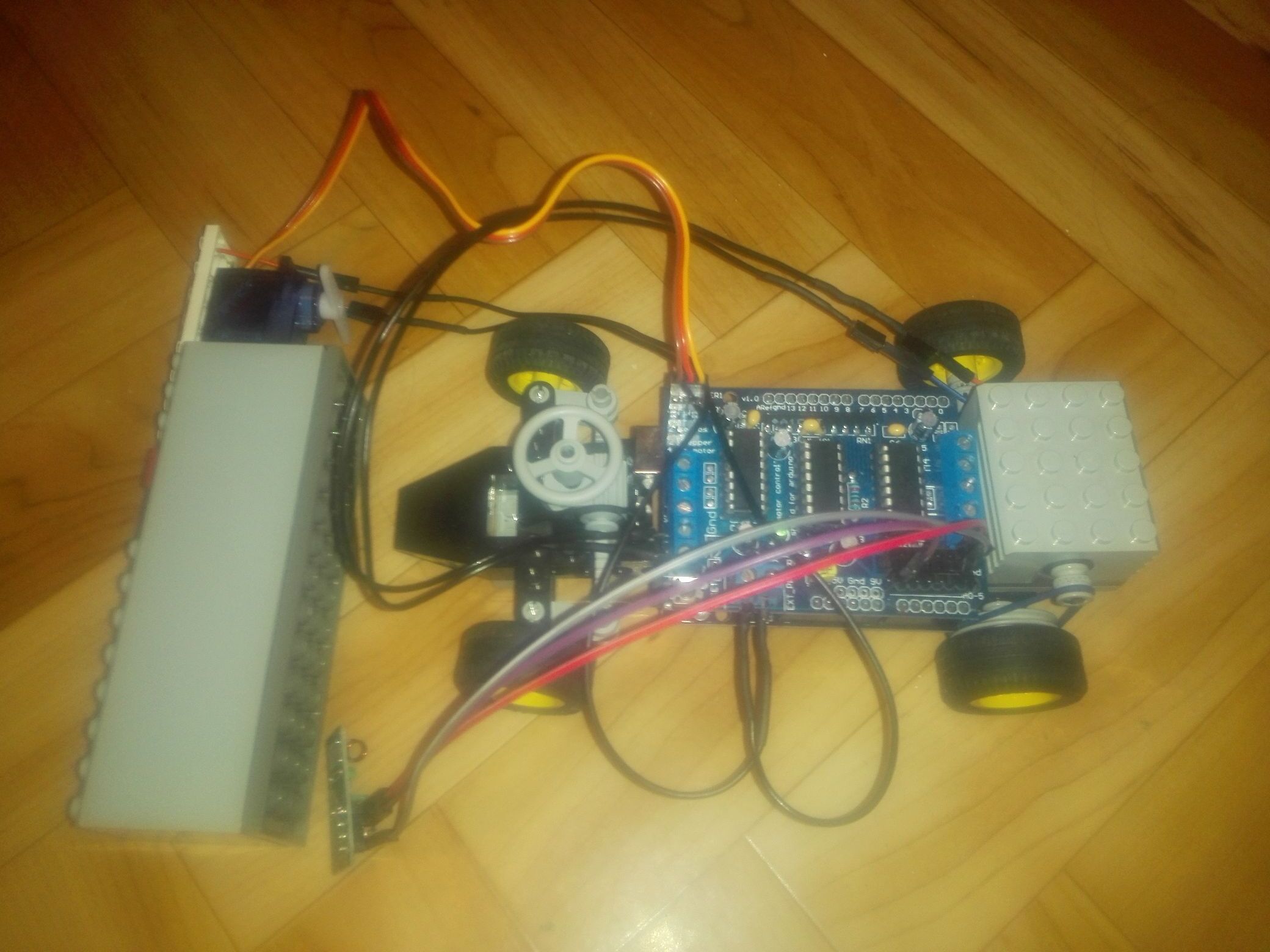
I think it is a code/library problem, so I posted it in this section. There is no schematic diagram, I hope, the pictures will help.
The code for the car/receiver is from different sources and as you can see I am not an expert. I did not include the code of the transmitter, because the transfer is working. Perhaps someone can analyse the problem and find the error.
// Simple example of how to use VirtualWire to receive messages
// Implements a simplex (one-way) receiver with an Rx-B1 module
//
// See VirtualWire.h for detailed API docs
// Author: Mike McCauley (mikem@open.com.au)
// Copyright (C) 2008 Mike McCauley
// $Id: receiver.pde,v 1.3 2009/03/30 00:07:24 mikem Exp $

#include <ServoTimer2.h>
#include <AFMotor.h>
#include <VirtualWire.h>

AF_DCMotor motor2(2, MOTOR12_64KHZ); // create motor #2, 64KHz pwm

#define ServoPin  9

int x_position;
int y_position;

ServoTimer2 servo1;


void setup() {

  // Servo
  servo1.attach(ServoPin);  // attaches the servo???

    // Inizialize Serial
    Serial.begin(9600);

    Serial.println("setup");

    // Due to lack of access to Digital Pins with Motor Shield in place, using Analogue A0 (Arduino Pin 14) as Digital
    vw_set_rx_pin(14);

    // Initialise the IO and ISR
    vw_set_ptt_inverted(true); // Required for DR3100
    vw_setup(2000);  // Bits per sec

    vw_rx_start();       // Start the receiver PLL running


    Serial.println("setup done");
}

void loop()
{
    uint8_t buf[VW_MAX_MESSAGE_LEN];
    uint8_t buflen = VW_MAX_MESSAGE_LEN;

    if (vw_get_message(buf, &buflen)) // Non-blocking
    {
        int i;
        int j;


  digitalWrite(13, true); // Flash a light to show received good message
  // Message with a good checksum received, dump it.
  Serial.print("Got: ");

  for (i = 0; i < buflen; i++)
  {
    Serial.print(buf[i], HEX);
    Serial.print(" ");
  }
    Serial.println("");
    digitalWrite(13, false);

    // Format is XnnnnYnnnnAnBnCnDn
    // X is X position of joystick as 4 digits
    // Y is Y position of joystick as 4 digits
    // A is A button on joystick. 0= Not pressed. 1 = pressed
    // B is B button on joystick. 0= Not pressed. 1 = pressed
    // C is C button on joystick. 0= Not pressed. 1 = pressed
    // D is D button on joystick. 0= Not pressed. 1 = pressed

    //Serial.println("");

    x_position = (1000 * (buf[1] - 48)) + (100*(buf[2] - 48)) + (10*(buf[3] - 48)) + (buf[4] - 48);
    y_position = (1000 * (buf[6] - 48)) + (100*(buf[7] - 48)) + (10*(buf[8] - 48)) + (buf[9] - 48);

    Serial.println(x_position);
    Serial.println(y_position);

    x_position = map(x_position, 0, 1020, 0, 180);     // scale it to use it with the servo (result  between 0 and 180)

    servo1.write(x_position);                           // sets the servo position according to the scaled value

    delay(15);            // waits for the servo to get there

    Serial.print ("Servo= ");Serial.println (x_position);


int S1 = map(y_position, 500, 1020, 0, 255);
int S2 = map(y_position, 500, 0, 0, 255);

if(y_position >= 500)
           { y_position = map(y_position, 500, 1020, 0, 255);
           int S1 =  constrain (y_position, 0, 255);
           motor2.run(FORWARD);
           motor2.setSpeed(S1);
           Serial.print ("Forward= ");Serial.println (S1);
           }
else if(y_position <= 500)
           {y_position = map(y_position, 500, 0, 0, 255);
           int S2 =  constrain (y_position, 0, 255);
           motor2.run(BACKWARD);
           motor2.setSpeed(S2);
           Serial.print ("Backward= "); Serial.println (S2);
           }

      }
}
Thank you very much in advance.