Light Bulb Checking with Attiny

Hello,

for my current CarDuino project, I would like to include a circuit that lets an Attiny slave check the car's headlight and taillight bulbs, and then report that data to the CarDuino's Atmega head unit master.

I'm a bit reluctant to cut the light bulbs' wires in half and run them through my circuit, and I also think non-invasive current sensors for the Arduino are a bit pricey, so I thought maybe a way to do it would be this:

So in essence, in order for the optocoupler to go HIGH, the light bulb must be intact, through which the optocoupler is grounded.

And to actually find out if a light bulb is broken, the bulbs will be checked in pairs... if the optocoupler for the left hand side light bulb goes HIGH but the one for the right hand side bulb doesn't, that will mean that the right hand side light bulb must be broken. The obvious drawback of this design would be that if both light bulbs are kaput, the Attiny won't know. But light bulb check devices in older cars usually worked just that same way, and nobody complained :wink:

Is my circuit diagram feasible, or am I missing something important? I'm a little iffy myself on whether the way I want the optocoupler connected to the light bulb wire would work, but can't put my finger on it at the moment.

You've got both ends of the optocoupler LED/resistor combo connected to the same point. No current will flow through it's LED.

OldSteve:
You've got both ends of the optocoupler LED/resistor combo connected to the same point. No current will flow through it's LED.

yes, that's what I couldn't put my finger on.

So the only way to do this really is either cutting the light bulb wires or using a non-invasive current sensing module?

I'm not saying cutting the light bulb wires couldn't be done safely... but it would introduce a possible failure point into the lighting system...

carguy:
So the only way to do this really is either cutting the light bulb wires or using a non-invasive current sensing module?

Yep. If you cut the wire, you'd need a low-value series (shunt) resistor for current sensing, then either a comparator (to a digital input) or feed the voltage developed across the resistor to an analogue input.

Thanks, oldsteve... you've been a big help with this project so far... (still working on correctly passing 16-bit integers via I2C, but otherwise I2C is now working reliably within my breadboard test rig of my future CarDuino).

Another idea I've had is using the light bulb check module of an old Audi A4 which I've still got on my desk at home... it's an invasive all in one module which monitors your low-beam headlamps, your tail lights and all three brake lights... using that module as my light bulb checking device would mean even if I cut the wires, I would put a piece of approved electrical engineering between them, if you know what I mean.

The only problem is, I haven't quite understood how that module passes its data to the car's main driver info system screen... I've opened the module, it's about the size of a cigarette pack and it's got little more than a microcontroller on an SMD board inside it. If it passes its data via CAN, I will probably be out of luck trying to use it for my CarDuino. Not sure what to make of it yet, but maybe I will try to figure out how and what it reports back to the driver info system...

Cheap and dirty brute force? not elegant, but workable.

LDR (or other light sensor) at each bulb. lamp-test to energize the bulbs (or tap the headlight switch).
When the switch is on, are the sensors indicating lamp on (if LDR's, are readings below some threshold)?
could even sense and report witch bulb is 'out'. threshold is to avoid false triggers from ambient light.

123Splat:
Cheap and dirty brute force? not elegant, but workable.

LDR (or other light sensor) at each bulb. lamp-test to energize the bulbs (or tap the headlight switch).
When the switch is on, are the sensors indicating lamp on (if LDR's, are readings below some threshold)?
could even sense and report witch bulb is 'out'. threshold is to avoid false triggers from ambient light.

Ha. Great minds.....
I was just thinking the same thing myself. It is messy though, and would need long wires and possibly an operation on the headlight enclosure.

Well, you could do this:

link for circuit

where the 1M is the resistance of the lightbulb, 1 is a shunt resistor, 100 is a resistor in series with the shunt and 50 is the parasitic resistance of the car battery... But in reality, the numbers are going to be different and they are going to change. You could probably guess the internal resistance based on the open circuit battery voltage. It might actually work if you amplified the voltage over the shunt with an opamp, but don't take my word for it!

Edit: basically you would be measuring the current flowing through a branch parallel with the lightbulb. This current would get smaller if the bulb is okay and larger if it's not...

Hen,

Fair idea, BUT,,, the hot resistance for an incandescent headlight bulb is around 40 Ohms. I think T34's are around 20-25 Ohms. a lot less than 1M.

123Splat:
Hen,

Fair idea, BUT,,, the hot resistance for an incandescent headlight bulb is around 40 Ohms. I think T34's are around 20-25 Ohms. a lot less than 1M.

Obviously, and the series resistance is going to be less than 50 ohms for a car battery! I would expect about 1mOhm. The numbers aren't even close to reasonable, they are orders of magnitude off. I just randomly typed some numbers in tbh. I should've put in the actual numbers, to see if this is feasible or not. It would probably show me that it's not even close. :smiley:

Edit: yup, not even close, sorry about that

Sooooo, I suppose using a photoresistor is the way to go...

So I had a closer look tonight at that light bulb check module that I've got which came out of an old Audi...

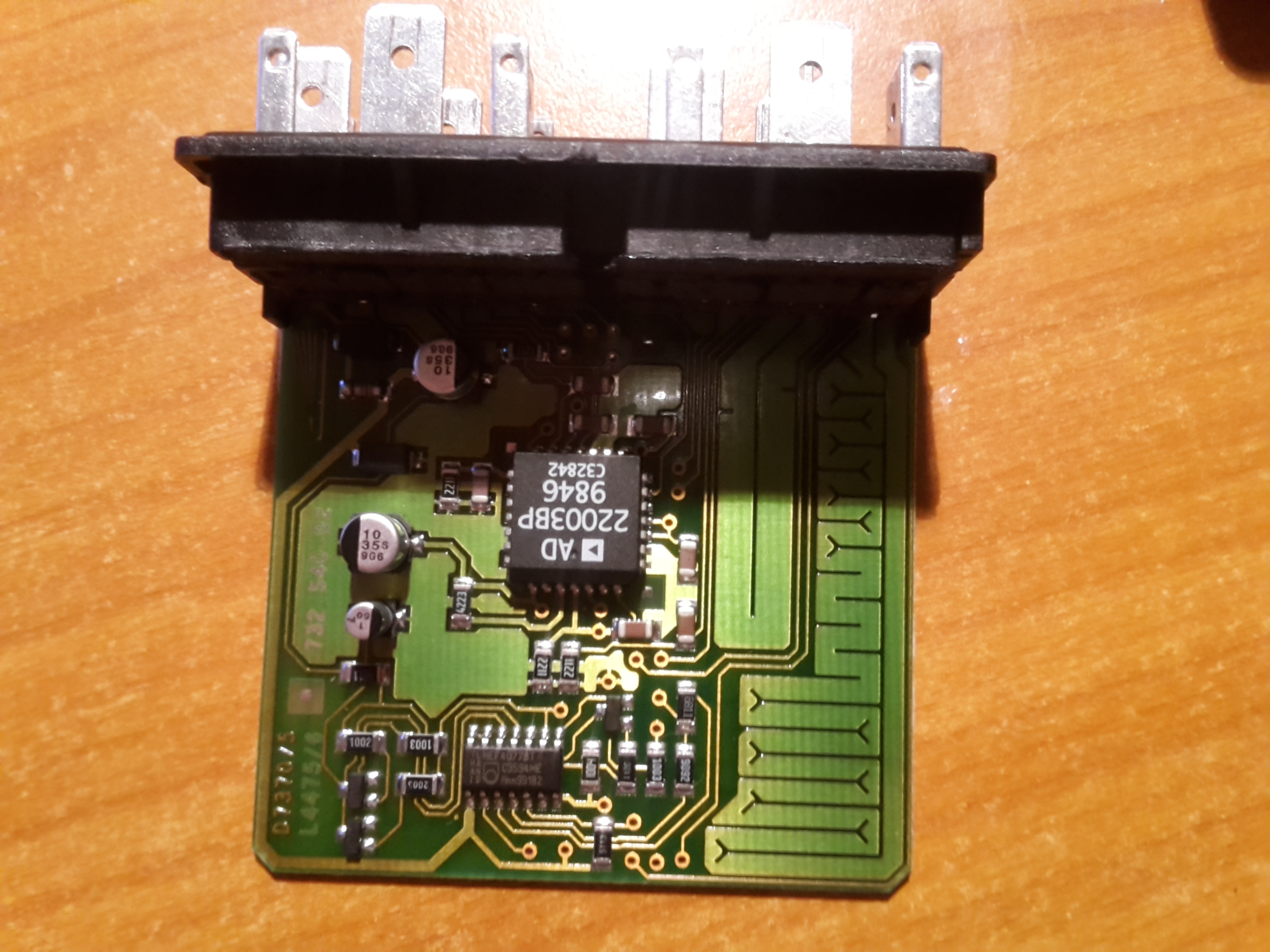
Here's a view of the opened light bulb check module (VW/Audi part no. 4BO 919 421):

At its core seems to be a Philips Quadruple exclusive-NOR gate shunt resistor (HEF4077BT). I'm not sure what to make of the IC in the center, but maybe you guys know more.

Anyway, here's a look at the pin terminal numbers:

Pin terminal numbers on German cars are standardized based on the DIN 72552 industrial standardization directive. For example, you can see pins 56bL and 56bL1 on the connector. 56bL stands for low-beam headlights, left hand side.

This module has one 56bL and one 56bL1 pin, meaning one of them must be where power goes in from the car battery and steering column light switch, and the other one is where it comes out again, and on to to the light bulb itself.

This module gives out broken light bulb warnings on the KS and KB pins in the top right corner of the picture. But, and here's the convenient part -- accoding to all the research I have done on Audi electrical circuitry tonight, these aren't data lines. Instead, one pin is for all of the exterior lights around the car except the brake lights, and the other one is for the brake lights. If pin KB goes high, it means there's something wrong with the brake lights, and if KS goes high, one of your taillights or headlights is broken.

This essentially means that you've only got two kinds of warnings that you can produce on a CarDuino screen, and it doesn't enable you to tell which of one your many exterior light bulbs is broken. It also won't tell you which brake light is gone.

But, as I've said - this would give me a ready-made module, an officially approved piece of electrical engineering to put in my car. Not that I don't have faith in my own ability to build and solder together my very own homemade light bulb check unit that can do the job, but using the Audi module would be an extra bit of reassurance.

And besides, here in Germany, these modules can be had used for €5 a piece on eBay. It'd be a challenge building my very own light bulb check module for that kind of price, taking into account all the different parts I'd have to buy...

The connector plugs could be slightly more difficult to come by, I will probably have to go to a few junkyards here in the area, looking for late-90s Audis where I could just cut them out of the central electrical panel looms.

EDIT:

I just thought of another approach... what if I pass a small 5V current from the Attiny (!) through the optocoupler, using a 10K resistor or similar, and then connect the GND side of the optocoupler to the wire going to the light bulb? That way, the optocoupler would be grounded through the light bulb, and would stay LOW if the light bulb is broken.

One issue that I am imagining with this approach though would be that it would affect the light bulbs' lifespans if there's a current constantly going through them, but again, that current would be minimal.

A high-side current sensor like the INA219 (26volt, with A/D) or IN169 (60volt, without A/D) is sensitive enough to detect the volt-drop of a piece of wire to the lightbulb.
Try to measure volt-drop of the wire from the light relay to the actual light bulb with a DMM.
Leo..

Wawa:
A high-side current sensor like the INA219 (26volt, with A/D) or IN169 (60volt, without A/D) is sensitive enough to detect the volt-drop of a piece of wire to the lightbulb.
Try to measure volt-drop of the wire from the light relay to the actual light bulb with a DMM.
Leo..

Yes, but one like this INA219 High Side DC Current Sensor Breakout - 26V ±3.2A Max [STEMMA QT] : ID 904 : $9.95 : Adafruit Industries, Unique & fun DIY electronics and kits will be $10 a piece... for that kind of price, I can almost get two ready-made, used Audi light bulb check modules on eBay... which would already contain a similar component like the INA219.

If you see a decent volt-drop with a DMM (0.25volt or more), then a simple (PNP) transistor could work.
Leo..

Wawa:
If you see a decent volt-drop with a DMM (0.25volt or more), then a simple (PNP) transistor could work.
Leo..

The downside of voltage drop sensing instead of current is that the warning will trigger if the headlights are on with the engine not running. (Which might be a good thing as a reminder.)

OldSteve:
The downside of voltage drop sensing instead of current....

I was talking about volt-drop along a piece of wire. Current sensing.
Leo..

Wawa:
I was talking about volt-drop along a piece of wire. Current sensing.
Leo..

Oh right. I misunderstood.
Easiest if it could be done on the low side, (similar to adding a sense resistor).

OldSteve:
Easiest if it could be done on the low side, (similar to adding a sense resistor).

Yeah, but not so easy in a car though.
Everything ground is almost directly connected to the chassis.
Leo..

Wawa:
Yeah, but not so easy in a car though.
Everything ground is almost directly connected to the chassis.
Leo..

That's where a series shunt resistor would be useful instead of sensing from the wire. It could go between the headlight and ground, with the Arduino GND connected to the car's ground for a common reference, and the high side of the resistor could go straight to an analogue input, (maybe with a series resistor and Zener to Arduino GND, in case the resistor ground became disconnected). Wire length would be irrelevant that way.
It gets harder when it's done on the high side, and more bits and pieces are needed.
Trouble is, it means tapping into the wiring to insert the sense resistor.

Either way, I think that carguy plans to go with the Audi module anyway. Personally, I'd go with a shunt resistor. I don't mind chopping into the electrics of my old bombs. :smiley:

It seems that the black box from post#10 contains a shunt resistor (the thick track with the fish-tails).
Leo..