I need to place a relatively large capacitor before a GSM module's power supply connection to prevent the voltage on the uC board from dropping significantly (I measured even 3,7 to 2,5V short drop) when the module is turned on. The issue is that sometimes this voltage drop causes the board to reset. However using such large capactor introduces the problem of charging the capacitor.
I'm still undecided on whether the capacitor should remain charged or not when the GSM module is not in use, as its leakage current could be saved in the latter case. Right now, I have a MOSFET high side switch doing the job of cutting power from the GSM board.
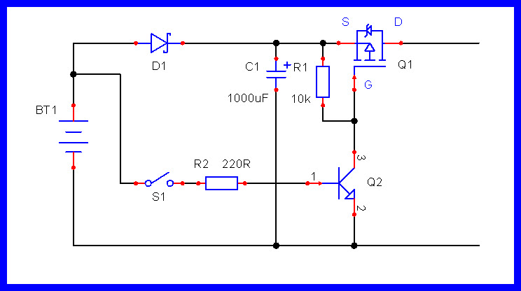
I have an idea for the case if the capacitor would remain charged all the time, I just need to use another MOSFET and a charging resistor:
Basically the R31/1k resistor would keep the large capacitor charged, and when needed, switching both MOSFETs on would allow unlimited current flow from VBAT to the GSM module.
Another approac would be to use a series inductor instead of doubled MOSFET, but I have no clue how to size this inductor.
Anyway I have already tried to hold a precharged buffer capacitor (1800uF) to the uC board power input terminal. Although this is not an optimal place for the GSM buffer capacitor, it already helped regarding the voltage drop.
Do you understand why the voltage drops? Perhaps easier to solve that problem than add bandaids. The problem is the internal resistance of whatever you are using for power. Change to a supply with a larger current rating which is the same as reducing the internal resistance of the current supply.
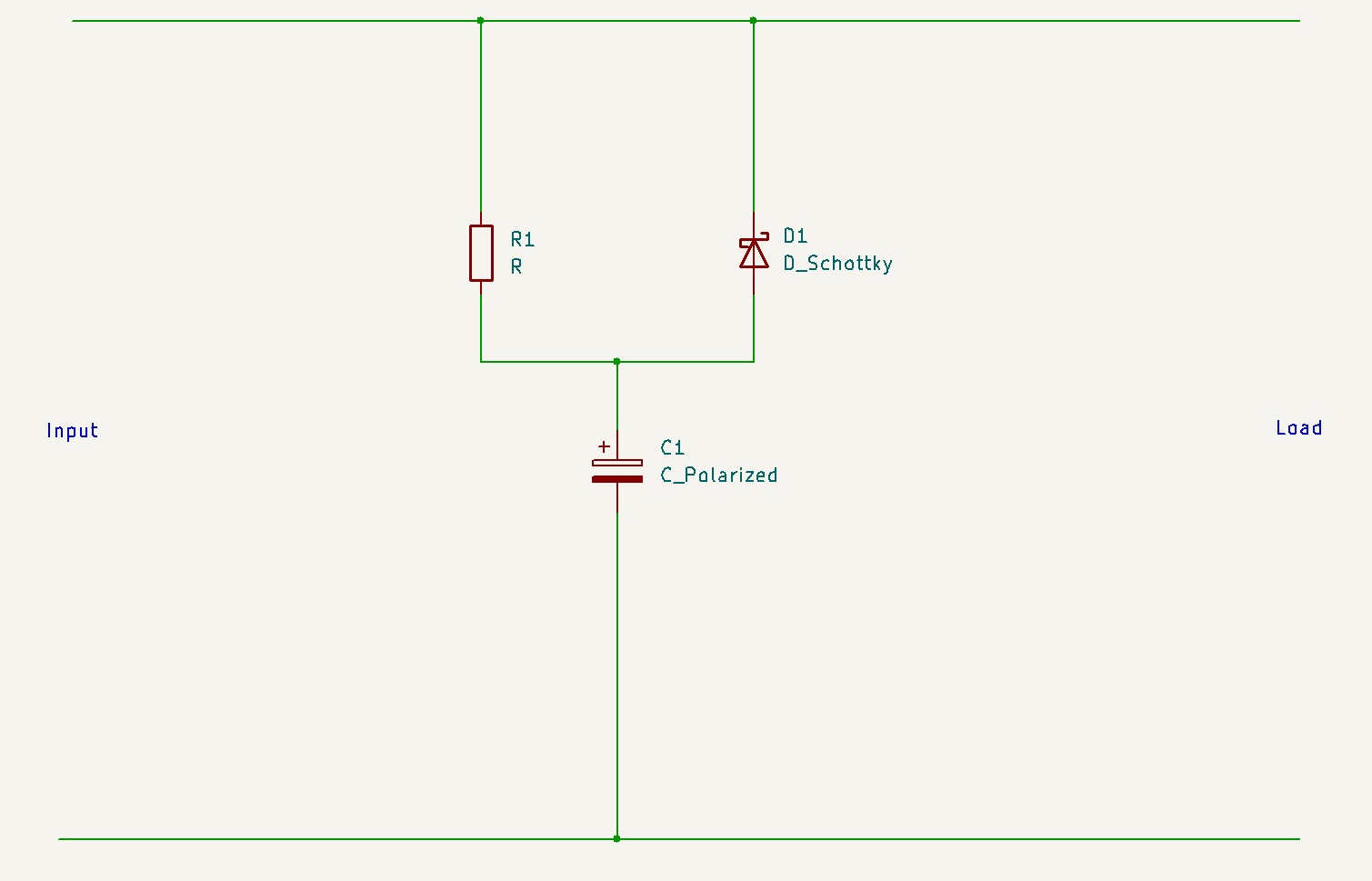
Put a diode between the capacitor positive and the positive supply so the diode points away from the capacitor. The capacitor can discharge through the diode but not charge. Put a resistor across the diode to charge the capacitor. To a good approximation the charge time of the capacitor is 5RC seconds, so use that as the basis for choosing the resistor value. Use a Schottky diode.
I don't have too many choices regarding the supply, it will be this type of cell: ER34615M.
Although you may be right in that I am currently testing with another type of chargable cell: NCR18650B.
Can you tell by the datasheets if the primary cell would make any difference?
Unfortunately they not arrived yet.
But as the turned on GSM module is operating it needs continous supply from the battery (through SWITCHED_VBAT on the schematic). The series resistor would limit the current and would reduce the efficiency with its voltage drop.
My understanding is you have a brief drop immediately after turning on the GSM module, the capacitor is to cover that dip. If it's not a dip but a continuous problem then your power supply isn't capable of enough current.
The resistor isn't in series with the GSM module, only the capacitor, to limit its charging, which I thought is what you asked for.
To prevent powering the GSM module though the 1k resistor when it is not needed.
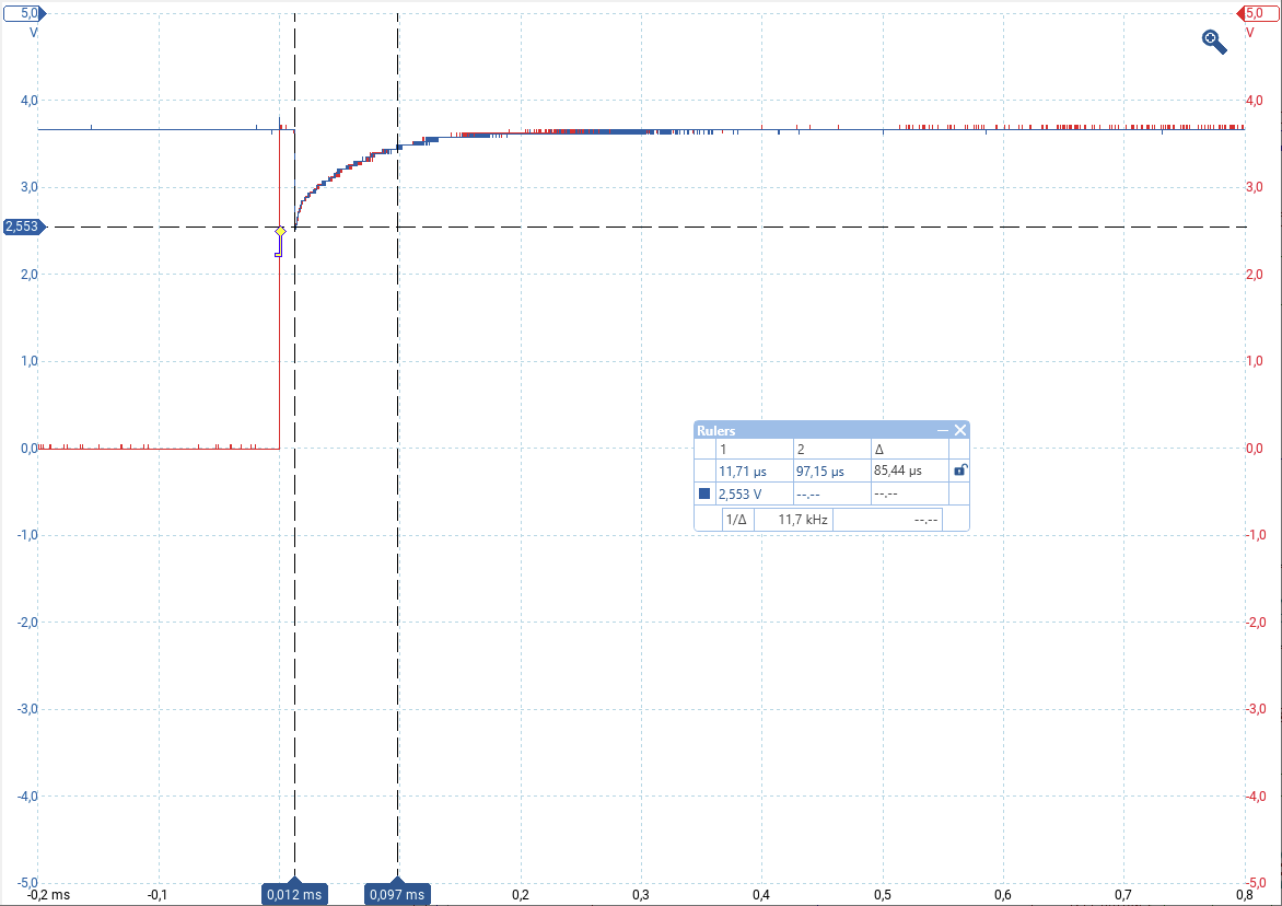
It's just a drop, like this:
Red signal rising edge is the switch on trigger for the MOSFET, blue is the measured voltage of the 33uC capacitor for the uC.
In the resulting PDF, the electrical characteristics show the rated discharge rate is 15ma. It seems to be made for an instrument memory backup battery.
What's the physical connenction?
Is your larger cap placed just next to the VIN of the module?
If you want to protect the board, why are you so focused on the gsm module?
Add a cap for the mcu/board, not the module.
Charge current is limited by R1, discharge is through D1, with a small contribution through R1, especially for the first 0.2V, which is the drop across the diode. Note that I chose a Schottky diode for its low voltage drop.
If I read your oscillosscope trace correctly you are only trying to cover 85μs, so I doubt you need anything like 2000μF.
I've seen an issue with this or similar module, where it would send itself into a loop due to the voltage drop it create during power up. And I think you're right to use a capacitor, but you can probably (to be tried out) get away with a much smaller one, like 20-40% of the F you have now, and to remove Q6 and R31. Also make sure you have enough trace-width from the battery to the module.
Bed reading if you or anyone like SIM7080G datasheet where pages 22, 23 are of interest. Note that this isn't the module you have but the chip itself.
Also pay attention to the watermark, trenchcoat and sunglasses on.