I want to make a both black and white line follower. I am new to arduino and programming . I have collected a code from online which is for following black line . how can I make it to follow a white line.
UTEH STR
Youtube Channel : https://www.youtube.com/channel/UCk8rZ8lhAH4H-75tQ7Ljc1A
Instagram :
- https://www.instagram.com/utehstr/
- utehstr
- Uteh Str
Email : teamuteh@gmail.com
*/
//----------------------------------------Include Library
#include "U8glib.h"
//----------------------------------------
//----------------------------------------Initialize u8g
U8GLIB_SSD1306_128X64 u8g(U8G_I2C_OPT_NONE|U8G_I2C_OPT_DEV_0); // I2C / TWI
//----------------------------------------
//----------------------------------------Defines the PIN for the Buttons
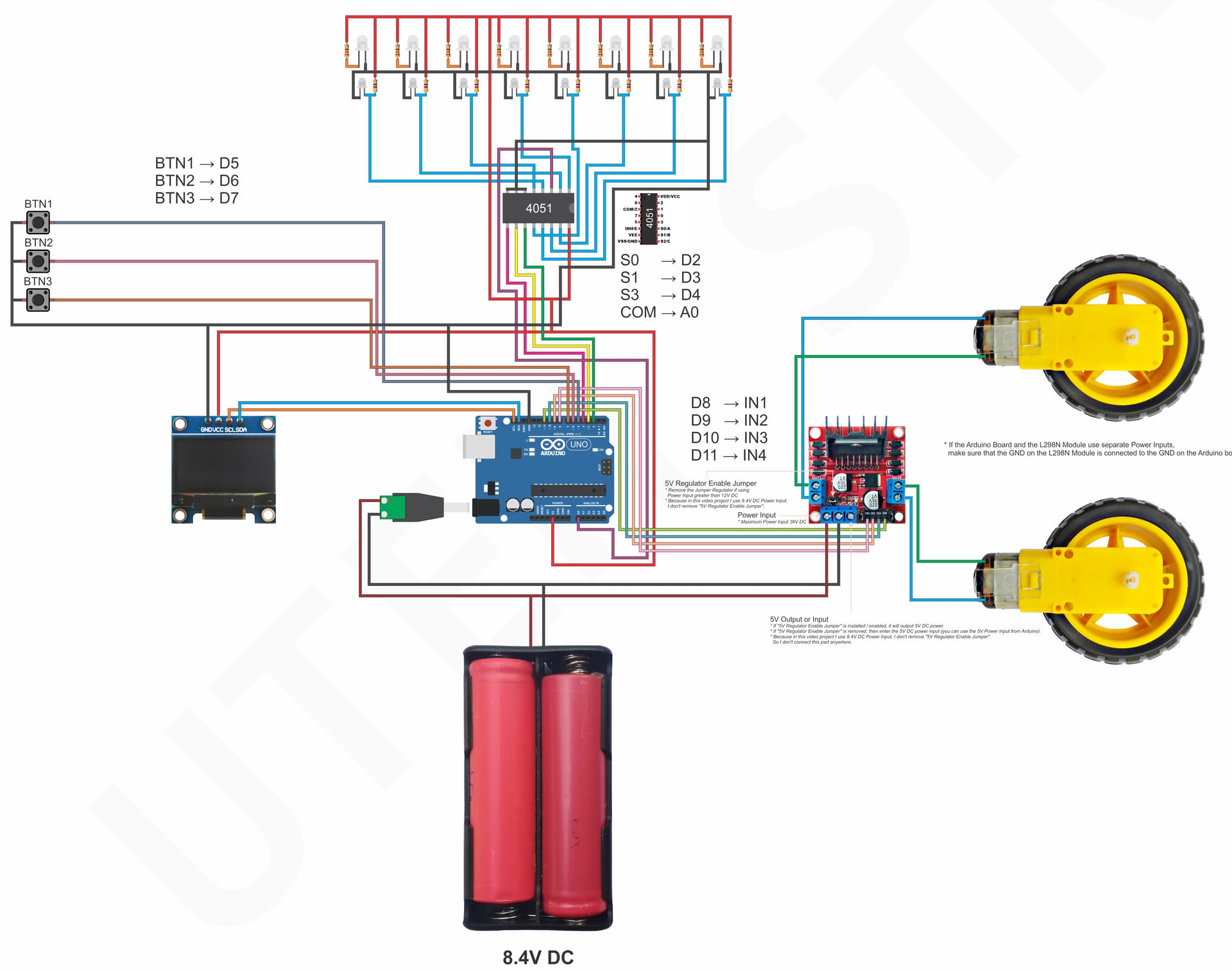
#define Button_Pin_1 5
#define Button_Pin_2 6
#define Button_Pin_3 7
//----------------------------------------
//----------------------------------------Variable for line sensors with multiplexer 4051
int Sensor_ADC_0[8];
bool bit_Sensor[8];
byte bin_Sensor = 0b00000000;
//----------------------------------------
//----------------------------------------Reference variable for the line sensor in order to determine the white and black lines or colors
int HighRef[8];
int LowRef[8];
int ResultRef[8];
//----------------------------------------
//----------------------------------------PIN declaration for the 4051 multiplexer
const int selectPins[3] = {2, 3, 4}; // S0->2, S1->3, S2->4
const int zInput = A0; //--> Connect common (Z) to A0 (analog input)
//----------------------------------------
//----------------------------------------Variable for Menu or Mode
bool calibration_mode = false;
bool sensor_check_mode = false;
bool start_mode = false;
//----------------------------------------
int calibration_process = 1; //--> Variable for the sequence of the calibration process
//----------------------------------------Variable PIN for the L298N motor driver
int Motor_L = 11; //--> D11->IN4 (To adjust the direction of the left motor rotation)
int Motor_L_PWM = 10; //--> D10->IN3 (To set the left motor PWM value)
int Motor_R_PWM = 9; //--> D9->IN2 (To set the right motor PWM value)
int Motor_R = 8; //--> D8->IN1 (To adjust the direction of the right motor rotation)
//----------------------------------------
int PWM_Speed = 200; //--> Variable for the PWM value
//----------------------------------------Configuration variables for KP, KI and KD values
// Actually there are several methods to determine the value of KP, KI and KD. You can find it on the internet.
// Motor speed, distance between sensor and motor, distance between right motor and left motor and others are some things that can be taken into account in determining the values of KP, KI and KD in line follower robots.
// My way to determine the value of KP, KI and KD is by manual or "Trial and Error".
int Kp = 10;
int Ki = 2;
int Kd = 100;
//----------------------------------------
int error, last_error; //--> Variable to hold error value of the line sensor
//========================================================================VOID SETUP
void setup() {
// put your setup code here, to run once:
//----------------------------------------Set up the select pins as outputs:
for (int i=0; i<3; i++)
{
pinMode(selectPins[i], OUTPUT);
digitalWrite(selectPins[i], HIGH);
}
//----------------------------------------
//----------------------------------------Buttons PIN as input
pinMode(Button_Pin_1, INPUT_PULLUP);
pinMode(Button_Pin_2, INPUT_PULLUP);
pinMode(Button_Pin_3, INPUT_PULLUP);
//----------------------------------------
//----------------------------------------Motor PIN as output
pinMode(Motor_L, OUTPUT);
pinMode(Motor_R, OUTPUT);
//----------------------------------------
u8g.setFont(u8g_font_unifont); //--> Sets the font for the OLED display
//----------------------------------------Initial display on OLED
u8g.firstPage();
do {
//u8g.drawFrame(0, 0, 128, 64);
u8g.setPrintPos(12, 14);
u8g.print("LINE FOLLOWER");
u8g.setPrintPos(43, 29);
u8g.print("ROBOT");
u8g.setPrintPos(55, 44);
u8g.print("BY");
u8g.setPrintPos(33, 59);
u8g.print("UTEH STR");
} while( u8g.nextPage() );
//----------------------------------------
delay(1000);
}
//========================================================================
//========================================================================VOID LOOP
void loop() {
// put your main code here, to run repeatedly:
//----------------------------------------MENU Display on OLED Display
if (start_mode == false) {
u8g.firstPage();
do {
u8g.setPrintPos(45, 14);
u8g.print("MENU");
u8g.setPrintPos(0, 29);
u8g.print("1. CALIBRATION");
u8g.setPrintPos(0, 44);
u8g.print("2. CHECK SENSOR");
u8g.setPrintPos(0, 59);
u8g.print("3. START");
} while( u8g.nextPage() );
}
//----------------------------------------
//----------------------------------------Conditions to start the line sensor calibration process
if (button(1) == LOW && start_mode == false) {
calibration_mode = true;
while (button(1) == LOW) {
delay(100);
}
calibration(); //--> Go to the calibration subroutine
}
//----------------------------------------
//----------------------------------------Conditions for checking line sensors and displaying on OLED Display
if (button(2) == LOW && start_mode == false) {
sensor_check_mode = true;
while (button(2) == LOW) {
delay(100);
}
//........................................
while (sensor_check_mode == true) {
check_Sensor(); //-->
u8g.firstPage();
do {
u8g.setPrintPos(16, 14);
u8g.print("CHECK SENSOR");
u8g.setPrintPos(33, 29);
printBinaryByte(bin_Sensor);
u8g.setPrintPos(0, 59);
u8g.print("1. BACK");
} while( u8g.nextPage() );
if (button(1) == LOW) {
sensor_check_mode = false;
while (button(1) == LOW) {
delay(100);
}
}
delay(10);
}
//........................................
}
//----------------------------------------
//----------------------------------------Conditions for stopping and starting the robot to follow the line
if (button(3) == LOW) {
start_mode = !start_mode;
while (button(3) == LOW) {
delay(100);
}
if (start_mode == true) {
u8g.firstPage();
do {
u8g.setPrintPos(40, 29);
u8g.print("START");
u8g.setPrintPos(0, 59);
u8g.print("3. STOP");
} while( u8g.nextPage() );
}
}
//----------------------------------------
//#################################################### PID CONTROLLER ####################################################
// To be honest, I don't really understand the concept of PID. I'm also still learning about this.
// So I can't write a detailed description of the PID.
// I got the PID formula from : https://create.arduino.cc/projecthub/mjrobot/line-follower-robot-pid-control-android-setup-e5113a
// You can visit the link above to get a more detailed PID explanation.
// I am aware that maybe the application of the results of the PID Calculation in this program code may still have many shortcomings.
// Please comment in the comments column of this video for criticism and suggestions :-)
if (start_mode == true) {
int PWM_Max_R = PWM_Speed;
int PWM_Max_L = PWM_Speed;
check_Error(); //--> Call the check_Error () subroutine to get an Error value.
//........................................PID calculations
int P = error;
int I = I + error;
int D = error - last_error;
int PID = (Kp * P) + (Ki * I) + (Kd * D);
//........................................
//........................................Applying the result of PID calculation to the driving motors.
int PWM_R = PWM_Max_R - PID;
int PWM_L = PWM_Max_L + PID;
PWM_R = PWM_R - PID;
PWM_L = PWM_L + PID;
last_error = error;
if (PWM_R >= 0) {
right_Forward();
} else {
right_Backward();
}
if (PWM_L >= 0) {
left_Forward();
} else {
left_Backward();
}
if (PWM_R < 0) PWM_R = 0 - PWM_R;
if (PWM_L < 0) PWM_L = 0 - PWM_L;
if (PWM_R > 255) PWM_R = 255;
if (PWM_L > 255) PWM_L = 255;
if (digitalRead(Motor_R) == LOW) {
PWM_R = abs(PWM_R);
} else {
PWM_R = 255 - PWM_R;
}
if (digitalRead(Motor_L) == LOW) {
PWM_L = abs(PWM_L);
} else {
PWM_L = 255 - PWM_L;
}
analogWrite(Motor_R_PWM, PWM_R);
analogWrite(Motor_L_PWM, PWM_L);
//........................................
}
//########################################################################################################################
}
//========================================================================
//========================================================================bool button(int btn_num)
// Subroutines for reading the conditions of the buttons
bool button(int btn_num) {
bool Button_Result;
if (btn_num == 1) Button_Result = digitalRead(Button_Pin_1);
if (btn_num == 2) Button_Result = digitalRead(Button_Pin_2);
if (btn_num == 3) Button_Result = digitalRead(Button_Pin_3);
return Button_Result;
}
//========================================================================
//========================================================================void check_Error()
// Subroutines to get error values for several conditions
void check_Error() {
check_Sensor(); //--> Calling the check_Sensor () subroutine
//----------------------------------------Filling the error value
if (bin_Sensor == 0b00000001) error = 13;
if (bin_Sensor == 0b00000011) error = 11;
if (bin_Sensor == 0b00000010) error = 9;
if (bin_Sensor == 0b00000110) error = 7;
if (bin_Sensor == 0b00000100) error = 5;
if (bin_Sensor == 0b00001100) error = 3;
if (bin_Sensor == 0b00001000) error = 1;
if (bin_Sensor == 0b00011000) error = 0;
if (bin_Sensor == 0b00010000) error = -1;
if (bin_Sensor == 0b00110000) error = -3;
if (bin_Sensor == 0b00100000) error = -5;
if (bin_Sensor == 0b01100000) error = -7;
if (bin_Sensor == 0b01000000) error = -9;
if (bin_Sensor == 0b11000000) error = -11;
if (bin_Sensor == 0b10000000) error = -13;
//----------------------------------------
}
//========================================================================
//========================================================================void right_Forward()
// Subroutine to make the right motor move forward
void right_Forward() {
digitalWrite(Motor_R, LOW);
}
//========================================================================
//========================================================================void right_Backward()
// Subroutine to make the right motor move backward
void right_Backward() {
digitalWrite(Motor_R, HIGH);
}
//========================================================================
//========================================================================void left_Forward()
// Subroutine to make the left motor move forward
void left_Forward() {
digitalWrite(Motor_L, LOW);
}
//========================================================================
//========================================================================void left_Backward()
// Subroutine to make the left motor move backward
void left_Backward() {
digitalWrite(Motor_L, HIGH);
}
//========================================================================
//========================================================================void calibration()
// Subroutines for the calibration process
void calibration() {
//----------------------------------------Configuration and initial display of the calibration process
calibration_process = 1;
u8g.firstPage();
do {
u8g.setPrintPos(20, 29);
u8g.print("CALIBRATION");
u8g.setPrintPos(0, 59);
u8g.print("1. Done");
} while( u8g.nextPage() );
for (byte i=0; i<=7; i++) {
HighRef[i] = 0;
LowRef[i] = 1023;
}
//----------------------------------------
//........................................................................
while (calibration_mode == true) {
if (button(1) == LOW) {
calibration_process++;
while (button(1) == LOW) {
delay(100);
}
}
//----------------------------------------Conditions to get the highest and lowest reference value of the line
if (calibration_process == 1) {
read_Sensor();
for (byte i=0; i<=7; i++) {
if (Sensor_ADC_0[i] > HighRef[i]) HighRef[i] = Sensor_ADC_0[i];
if (Sensor_ADC_0[i] < LowRef[i]) LowRef[i] = Sensor_ADC_0[i];
}
}
//----------------------------------------
//----------------------------------------Conditions for obtaining the reference result value
if (calibration_process == 2) {
for (byte i=0; i<=7; i++) {
ResultRef[i] = HighRef[i] + LowRef[i];
ResultRef[i] = ResultRef[i] / 2;
}
u8g.firstPage();
do {
u8g.setPrintPos(20, 29);
u8g.print("CALIBRATION");
u8g.setPrintPos(20, 44);
u8g.print("IS COMPLETE");
} while( u8g.nextPage() );
delay(1000);
calibration_process = 3;
}
//----------------------------------------
//----------------------------------------Conditions for checking sensors based on the results of the calibration
if (calibration_process == 3) {
check_Sensor();
u8g.firstPage();
do {
u8g.setPrintPos(16, 14);
u8g.print("CHECK SENSOR");
u8g.setPrintPos(33, 29);
printBinaryByte(bin_Sensor);
u8g.setPrintPos(0, 59);
u8g.print("1. BACK");
} while( u8g.nextPage() );
delay(10);
}
//----------------------------------------
//----------------------------------------Conditions for returning to the void loop (calibration process is complete)
if (calibration_process == 4) {
calibration_mode == false;
return;
}
//----------------------------------------
}
//........................................................................
}
//========================================================================
//========================================================================void check_Sensor()
// Subroutines to check sensors based on the calibration result value (ResultRef)
void check_Sensor() {
read_Sensor(); //-->
//----------------------------------------Specifies a bit_Sensor array for HIGH or LOW
for (byte i=0; i<=7; i++) {
if (Sensor_ADC_0[i] > ResultRef[i]) {
bit_Sensor[i] = HIGH;
} else {
bit_Sensor[i] = LOW;
}
}
//----------------------------------------
//----------------------------------------inserting the bit_Sensor array into the bin_Sensor binary
for (byte i=0; i<=7; i++) {
bitWrite(bin_Sensor, i, bit_Sensor[7-i]);
}
//----------------------------------------
}
//========================================================================
//========================================================================void read_Sensor()
// Subroutines to read sensor values in the form of ADC values
void read_Sensor() {
for (byte pin=0; pin<=7; pin++) {
selectMultiplexerPin(pin); //--> Select one at a time
Sensor_ADC_0[pin] = analogRead(A0); //--> and read Z
}
}
//========================================================================
//========================================================================void selectMultiplexerPin(byte pin)
// Subroutines to determine which pins or channels to read from the 4051 multiplexer
void selectMultiplexerPin(byte pin) {
for (int i=0; i<3; i++) {
if (pin & (1<<i))
digitalWrite(selectPins[i], HIGH);
else
digitalWrite(selectPins[i], LOW);
}
}
//========================================================================
//========================================================================void printBinaryByte(byte value)
// Subroutine for displaying sensors in binary form on an OLED Display
void printBinaryByte(byte value) {
for (byte mask = 0x80; mask; mask >>= 1) {
u8g.print((mask & value) ? '1' : '0');
}
}