Hello,
I'm new here and to the wonderful world of microcontrollers. I've been looking around for a while at various ways of building an FSX flight deck (one step short of a true simpit) and determined the Arduino Mega would likely be the best board for my needs.
But before I can start plugging stuff up, I have a couple of questions.
First, I plan to use RadioShack Linear-taper potentiometers for my axes (pitch, roll etc.) but I'm not sure what ohm value to buy, I was thinking of 100k ohms which would provide greater resistance per bit of analog resolution, but I'm not sure if a lower value would be better.
Second, to "cheat" and get even more digital input/outputs than the Mega naturally has, I thought about using an LED or Button matrix (whose ultimate physical arrangement likely would not be a matrix). LED matrices I sort of get, set the Anode line high, and play with the Cathode line, but button matrices confuse the heck out of me.
Looking at a button matrix would one of the lines be configured as output HIGH then record when the corresponding input goes LOW or are they both inputs or what?
Thanks for any help you can provide. The Arduino won't get here for a week or so, so maybe some of this will make sense once I start plugging wires up and slowly working up to a flight deck.
-Matt
Richard: Thanks for the heads up, I will now use the 10k pots instead of 100k. Also, the multiplexer sounds like an interesting idea, but I have no idea how to implement it on my own. I am Computer Science as opposed to Computer Engineering so I only know how the hardware works enough to make my software work :P. Is there a link or something that explains this concept? I've done some creative Googling, but am unsure exactly what to be looking for.
Mike: Thanks for the link, it looks like you're using the shift register idea too, but I'm still a tad unsure how to implement it.
Unfortunately, I may be limited to going out to a store and buying what I need instead of ordering it except in certain circumstances, so a direct-wired matrix may be what I have to stick with for now.
Thanks,
Matt
I'm just going to have to put the button matrix aside for now and concentrate on getting my project running then make it fancy.
Back to potentiometers, I'm a tad concerned about over-currenting the Arduino.
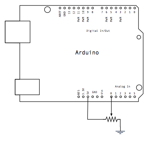
Based on this circuit diagram: http://arduino.cc/en/uploads/Tutorial/Graph_schem.png
a potentiometer is hooked up to the Arduino with the outer terminals going to 5v and ground, and the center terminal going directly to an analog input pin. Now since a potentiometer in this configuration is a voltage divider with one side giving 5v on the middle pin and the other giving 0v, wouldn't I need a resistor in series with the 5v pin of the potentiometer to limit the current to the input pin? 40mA limit would mean a 125ohm resistor right?
Thanks,
Matt