Power_Broker:
What? Of course a resistor divider does.
No it does not. A resistive divider changes proportional to the input voltage. If you actually read the OP, you would know that that is not what is being requested. Here is the requirement, verbatim:
I have a circuit that starts at 3.5V and progressively increases to 8V
I'd like it to start at 0.5 and increase to 5Vso essentially I'd like to wash 3V off the circuit .
From the ranges given, it is obvious that "wash" means "subtract". A resistor divider doesn't subtract, it divides (fancy that). The various suggestions to use diodes or allanhurst's suggestion to use a shunt regulator are much better at satisfying the criteria OP asked for.
...Which unfortunately doesn't look like it's what the OP needs. X-Y problem and all that. It's not necessarily about subtracting voltage, but combining two inputs in a harmonious way. That's a much more difficult issue to deal with.
Does the TCU properly control the solenoid with your circuit disconnected? I am wondering if your circuit damaged the TCU.
Normally "solenoids" are on/off devices. Either 0 Volts or their operating voltage is applied to them. Is this solenoid something different that actually gives variable amounts of motion with varying applied voltages?
JohnRob:
Question regarding the TCU. I'm more familiar with ECU and I'm thinking other automotive controllers must have the same limitation.
Are you sure the voltage is 0.5 to 3.5? Or could it be a PWM signal that seems to measure 0.5 to 3.5 with a voltmeter?
JohnRob
Exactly, what type of DMM do you have?
Does it have a Freq Hz and Duty % function.
Can you do those voltage measurements again, but with the DMM in AC Volts mode?
Thanks.. Tom..
JohnRob:
Question regarding the TCU. I'm more familiar with ECU and I'm thinking other automotive controllers must have the same limitation.
Are you sure the voltage is 0.5 to 3.5? Or could it be a PWM signal that seems to measure 0.5 to 3.5 with a voltmeter?
JohnRob
Sorry but yes you are 100% correct. The solenoid is controlled by a PWM signal after looking further into it.
I have measured the resistance through the solenoid and it is 5 ohms.
Sorry for the frustration this has caused. I really appreciate the assistance.
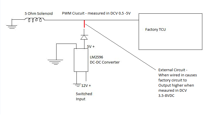
It is in fact a PWM switched circuit. When I remove the external input I added it operates as normal. But when I wire in the external supply and the TCU operates as it usually would the measure voltage in the circuit is 3VDC higher than it usually is and the operation of the system is much harsher which makes sense as it is not quite so gently modulated.
Assuming the TCU PWM circuit applies a high voltage or an open voltage the following will occur. When the TCU switches from high to open the ungrounded end of the solenoid will be driven in the negative direction due to the inductance of the solenoid. I am guessing that the high and low switching voltage that occurs at the solenoid terminal is charging the output capacitor or your PWM circuit through it's switching inductor and switching diode. The end result is a positive voltage getting generated on the output capacitor of your PWM circuit which causes the average voltage of the solenoid to increase when your circuit is connected.
I think your best bet would be to replace the diode that is in series with the PWM circuit with a relay. A P- Channel MOSFET would not work because of the reverse diode that is part of the MOSFET. Without knowing more details of the TCU circuit and the solenoid adding any circuitry to the solenoid pin risks affecting how the circuit functions.
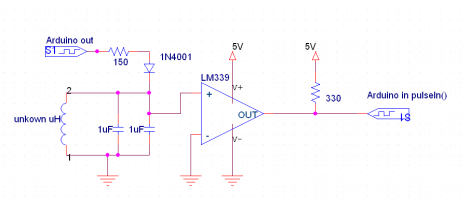
Since the OP doesn't have a scope, it might be helpful if he used a voltage divider to measure the voltage across the solenoid with an analog input and plot the values using Excel.
Test-1: Plot of solenoid voltage with ONLY ECU
Test-2: Plot of voltage with Buck converter connected.
Test-3: Plot of voltage without ECU.
Note: Measured analog counts should be converted to voltage before printing to serial port.
eewoz:
I think your best bet would be to replace the diode that is in series with the PWM circuit with a relay. A P- Channel MOSFET would not work because of the reverse diode that is part of the MOSFET. Without knowing more details of the TCU circuit and the solenoid adding any circuitry to the solenoid pin risks affecting how the circuit functions.
A changeover relay. You need to disconnect the TCU when you connect your control signal. There is a chance that the TCU will detect the open circuit though and flag a fault. Switching in a dummy load might be necessary to keep the TCU operating properly while you are overriding it.
eewoz:
Assuming the TCU PWM circuit applies a high voltage or an open voltage the following will occur. When the TCU switches from high to open the ungrounded end of the solenoid will be driven in the negative direction due to the inductance of the solenoid. I am guessing that the high and low switching voltage that occurs at the solenoid terminal is charging the output capacitor or your PWM circuit through it's switching inductor and switching diode. The end result is a positive voltage getting generated on the output capacitor of your PWM circuit which causes the average voltage of the solenoid to increase when your circuit is connected.
I think your best bet would be to replace the diode that is in series with the PWM circuit with a relay. A P- Channel MOSFET would not work because of the reverse diode that is part of the MOSFET. Without knowing more details of the TCU circuit and the solenoid adding any circuitry to the solenoid pin risks affecting how the circuit functions.
Hi Eewoz,
I replaced the diode with a relay and this is what has occurred:
For the TCU to normally operate the solenoid the following conditions must be met:
Road Speed - 75km/h - 150km/h
-Trans in gear
-Foot off brake
-TPS (throttle position sensor) between 10-70%
The TCU controls the solenoid under factory demanded conditions which is great.
When I switch my input and the factory system has not met its demanded conditions the system works fine.
However if I switch my input and and the TCU also has all conditions met and activates the solenoid the "combined" voltage is back up 8VDC again.
I also went a step further and when I switched my manual input in, I used a replay to switch out the Input from the TCU. The problem then is that the TCU creates a fault to Open circuit as it is looking for a 5-9 ohm resistance solenoid to activate.
On another track, is there a way to replicate the "solenoid" I also attempted to connect a 5ohm 10 watt resistor the the switched TCU circuit but it got far too hot. I added 6 more parallel resistors equaling 60 watts and still at 5 ohms but they drew 1.5 Amps and got hot still.
I think as its a PWM circuit a resistor will not be the best solution.
You work fast. What was the state of the system when the single 5 Ohm resistor got hot? Was just the TCU driving the solenoid or was both the TCU and your circuit driving the solenoid?
You work fast. What was the state of the system when the single 5 Ohm resistor got hot? Was just the TCU driving the solenoid or was both the TCU and your circuit driving the solenoid?
Just the TCU was driving the resistor. I have also carried out some further research into this system. It appears that it uses a current sense PWM monitoring circuit to apply current relative to monitored output.
So essentially I need to emulate the load that the coil would place on the circuit and provide monitor feedback.
Has anyone dealt with this style of circuit before?
mack85n:
Sorry but by big and fat, how many H would you recommend?
I haven't dealt with inductors much before.
Something comparable to the solenoid coil. Maybe find a relay with about a 5 ohm coil and use that as the dummy load instead of the resistor. Or wrap your own wire around a chuck of steel.
mack85n:
Just the TCU was driving the resistor. I have also carried out some further research into this system. It appears that it uses a current sense PWM monitoring circuit to apply current relative to monitored output.
So essentially I need to emulate the load that the coil would place on the circuit and provide monitor feedback.
Has anyone dealt with this style of circuit before?
Thanks,
I wonder if the TCU would flag an error in response to a short circuit on its output.
There are some real mysteries here. Earlier you said that the solenoid draws 600 mA yet when the TCU drives a 5 Ohm 10 Watt resistor the resistor overheats. It would take 1.4 Amps to dissipate 10 W into 5 Ohms and even more to cause the resistor to overheat.
TI makes a fancy solenoid driver IC that can detect faulty solenoids using a back EMF technique, detects faulty plunger movement, and undervoltage. Depending on exactly what is inside the TCU it may take another solenoid to fake it out.