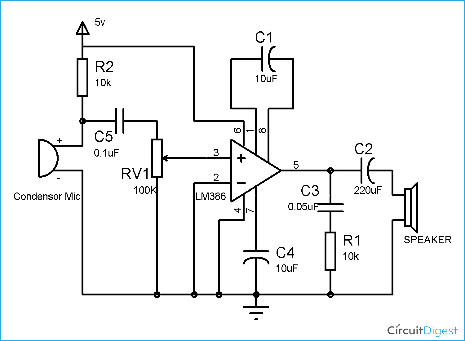
Hello, below i have an lm386 based audio amplifier. I have built the circuit as shown from here.
My circuit works but there is a lot of noise especially when i adjust the volume with the potentiometer. I notice that if i move away from the breadboard there is no noise and as my hand gets closer to the circuit, especially the mic it starts to whine at a very high frequency.
With my beginner knowledge of electronics, I believe that i must implement a bypass or de-coupling capacitor. but i tried using a 103 ceramic capacitor across the condenser mic( which didn't work) then i tried putting the capacitor between the positive and negative rails(which also didn't work).
Correct me if im wrong but this is a static voltage issue?
and also ........from what you say , this looks like a shielding issue - make the circuit on some strip board and mount it inside a metal tin connected to the 0v line .
The power supply could be an issue too - for example USB connection to a computer can be very noisy . Try it on batteries to check that out .
jremington:
That is most likely due to audio feedback between the speaker and the microphone. You have heard the effect many times on stage setups.
Move the speaker further away from the microphone, and point the mike in a different direction.
Noise during volume adjustment indicates a poor quality volume control.
It might help to add a large electrolytic cap across the power supply (220-1000 uF).
I acutally love electronics when i trouble shoot and figure certain things out....
I tried what you said and moved the mic away from the speaker and it didnt really help much and also noticed that the noise increases when i put my hand anywhere near the wires of the circuit.
Then i thought to myself that i am walking around in socks on a carpet, so i must have a high positive charge, Then i remembered from watching a youtube video that you can ground yourself by touching the benchtop power supply(which is what i am using)
then with one hand on the powersupply , it immediatly cuts out all noise and i am able to adjust the potentiometer with my other hand with zero problems.
hammy:
and also ........from what you say , this looks like a shielding issue - make the circuit on some strip board and mount it inside a metal tin connected to the 0v line .
The power supply could be an issue too - for example USB connection to a computer can be very noisy . Try it on batteries to check that out .
Im not 100% what shielding means? something with bad grounding?
Its funny that you mention that because, i had just messaged JRemington that i realized that i was walking around a carpet with socks on and when i would move my hand close to the wires of the circuit it would scream, then I realized that i am positively charged, then i put one hand on my benchtop power supply that i am using to power it and with my other hand i can move it by the circuit with no noise problem.
So i am not properly grounded. So what can i implement into the circuit so that this wont be a problem? Is that what shielding does?
As drawn the amplifier will have a gain of about 200. The circuit and minor variations I remember from about 1980 in Radio Shack's Engineers Notebook by Forest M. Mimms III. I also suggest changing R1 to about 10 Ohms.
You may want to think of yourself as a large antenna and the noise you are picking up is coupled to your amplifier. Your amplifier not only amplifies the input signal by 200 but any noise your body couples. This is more than likely just noise like 60 Hz (US & Canada) or 50 Hz (Euro and other locations) rather than static. The idea behind "shielding" is to block external noise and when making circuits on a breadboard they become very susceptible to external noise. Sort of a nature of the beast.
The high frequency squeal I learned as "feedback" and is, as was nicely explained, when the audio out feeds back into the microphone (audio in) and starts going around in circles, real fast.
Hard to believe the little LM386 has been around over 40 years. The data sheet can be found here if you get curious about the gain and how it is set.
As to the series resistor and cap, if I recall correctly they form a Zobel network normally found in audio amplifier circuits to counter the to counter the voice coil inductance of speakers but I never worked in audio so hopefully someone else can follow that up.
You have a decoupling cap on pin 7 which is good, but the input network connects direct to 5V
rail. Split R2 into two 4k7 resistors and add 100uF decoupling cap at their junction to ground to
clean up the input signal.
Also RV1 is rather high, and might create noise (hiss). something like 22k might be better if that's the case.
TomGeorge:
Hi,
Can you post a picture of your project so we can see your component layout.
I hope you haven't tried to cramp everything into a very small space.
It’s Boucherots cell designed to cancel the effects of inductance from the speaker. It makes the impedance look likes it’s not changing with frequency which makes it easier to drive. It provides damping and prevents oscillation.
wolframore:
It’s Boucherots cell designed to cancel the effects of inductance from the speaker. It makes the impedance look likes it’s not changing with frequency which makes it easier to drive. It provides damping and prevents oscillation.
I get that the speaker has inductance because it is a small coil of wire, and i get that the frequency changes due to someone talking into the mic. I don't get the part where the impedance changes with the frequency and why that is bad and makes it harder to drive?
Could you explain that part more, please?
Maybe has to due with oscillation and using the capacitor's capacitive reactance to cancel out the inductive reactance from the speaker?