Hello everyone, I have a project to control the air conditioner using arduino and ir led, however the problem I have is that I cannot transmit the air conditioner control signal at a long distance, the farthest is only 1.5m. Please give me a reference for the circuit to transmit IR signal at a long distance. The circuit I am using includes a 2N222 transistor, a 22Ohm resistor connected to the IR led and then connected to pin C of the transistor, pin C power is 5V, pin B is connected to a 6k8 Ohm resistor and then connected to the 3.3V arduino output.
6k8 is too high.
Try 220...
I presume 5V is connected to the led, not the transistor... a schematic would be very helpful...
- Always provide us a schematic showing all the components and interconnections.
- Two IR LEDs can be controlled by the same transistor.
- Design for 100mA IR current.
- Ensure the transistor saturates using a DMM.
To maximise the range, you need to maximise the current. So you need to know the maximum current of the led. This is not the the maximum continuous current, because, being used as an IR transmitter, it won't be continuously lit, even when it is transmitting. They are switched on and off at a particular frequency. That's how the receiver is able to distinguish them from background IR radiation. Used like this, the led can tolerate more than the max continuous current.
Do you have a model number, or any specs of the led, or, best of all, a datasheet?
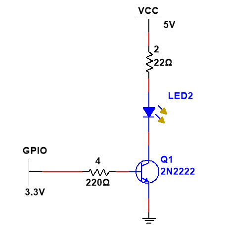
I use TSAL6100 led, my current diagram is like this, I just need the led to emit enough power to be able to control the air conditioner at a distance of 3m in the room, I will fix this ir control system on the wall opposite the air conditioner
At first I used a led that could withstand a current of 10-20mA, a voltage of 1.2V-1.5V, but it seemed to only work about 1.5m and had to be brought in immediately for air conditioning. So I plan to use TSAL6100 led, I need advice on the circuit to emit the best led, ensuring that the components and microprocessor are safe.

Put a parabolic reflector behind the led. Or even a flat one.
Car headlight reflectors using elliptical reflectors work well.
Aluminum foil reflects IR well. A simple rolled cone might work.
The problem is very likely to be something else, like the wrong IR carrier modulation frequency.
This is just a guess, because there is little to no useful information in this thread.
For help on this forum, please read and follow the instructions in the "How to get the best out of this forum" post.
It can still be controlled but at a close distance. I hope everyone can guide me so I can control the air conditioner at a long distance because my knowledge is still weak and there are still many mistakes.
Please read post #8 and provide useful information: air conditioner model, circuit diagram, links to the components, code posted using code tags, etc.
I have provided the circuit diagram and LED parameters in the previous answers. Toshiba RAS-255PR air conditioner.
#include <IRremoteESP8266.h>
#include <IRsend.h>
#include <ir_Toshiba.h>

#define IR_LED 4

IRToshibaAC ac(IR_LED);

void setup() {
  Serial.begin(115200);
  ac.begin();


  ac.on();
  ac.setMode(kToshibaAcCool);
  ac.setTemp(17);
  ac.setFan(4);
  ac.send();

}

void loop() {

  ac.send();
   delay(1000);
}
Here is the link to the data sheet.
It would have been helpful for you to have posted this.
Your transistor circuit should allow about (5V-1.35V-0.7V)/22 = 130mA current to flow through the led. The base current will be about (3.3V-0.7V)/220 = 11mA. These values seem ok and should give more than 1.5m range I think.
So the problem could be the base carrier frequency as mentioned by @jremington. If the wrong frequency is used, the receiver will be much less sensitive, even though the transmitter is sending a strong signal.
To know the correct carrier frequency for the receiver, you need to know it's model number. This may be shown on an internal schematic diagram for the air conditioner. Using the receiver model number, you can find it's carrier frequency from its data sheet.
If you cannot find that, it might be possible to test a range of commonly used carrier frequencies to see if any of those give more sensitivity and range.
Sorry, I missed that you said you plan to get this led. I incorrectly thought you have already tried this led and circuit and got only 1.5m range.
I think your plan should be good. You could try this circuit with your existing led. Many IR LEDs have similar specs. If the circuit damages your existing led, you can go ahead with your plan to buy the TSAL6100.
Two IR LEDs in series will give you almost 1.5 times the distance for the same LED current.
Leo..
I would assume that his Toshiba IR library has the correct carrier frequency. And if his code works, even at 1.5m, it's probably good. But I'm not clear whether he has actually tried the 22R resistor. If he got even a little distance with the original 220R, the new circuit really should work.
I was thinking the same thing, since he has 5V available. But then the resistor would be reduced to around 10R to keep the same current.
But could you provide the math on the effect on distance? Is it just the square root of the power multiple (inverse square law)?
In that circuuit I would use two LEDs in series and a 18 Ohm resistor.
Assuming Vf of 1.6volt of the LEDs at that current, it would top a safe 0.1A.
Practical distance could be 10m (I have worked with thousands of remote controls).
Doubling LEDs is AFAIK indeed the inverse of square root. Same as doubling current.
Leo..
I would expect successful 3m range with the circuit posted. Are you sure it's TS6100? Are you aware that the angle is quite narrow?
If you are careful not to give anything else than that short signal pulse to LED, you can go much lower with the LED series resistor.
And make sure that 5volt rail is properly buffered (with a 470uF+ capacitor).
Leo..