I'm not really looking for an answer to my specific issue I'm facing but more of knowledge on what to look at outside of my scope.
I have 3 tasks on an ESP32-S3-WROOM-1-N16R8 that I have running. But it dies and falls in to a reboot loop after a few minutes. I gave the tasks way more memory than they needed and have been monitoring it, but never gets low. Well not with in the 3 or so minutes it lives. But when I pull the power and reconnect it runs fine again for a similar amount of time.
All my tasks run on core one and I vTaskDelete(NULL); the loop(). I get not Guru messages or dumps and the package and all sensors get the full V and I that they need. (Old board had an issue when spinning up the WiFi and not getting enough current and was browning out)
So is there an area or something that I don't know about that I need to read up on? Googling for a few days trying to get around this issue and decided to ask
also the stack trace, which you normally get after a crash, gives some useful information even without using the analysis tool, say watchdog timer timeout etc. Strange you don't see this.
Plausible would be an array bound problem causing setup() to execute or similar.
Something doesn't make sense. You are posting for the first time, yet instead of Hello World, you have a multi-file tasking sketch. That is quite advanced, and anyone who can handle that would also know how to debug. Can you help us understand these seemingly contrary observations?
One other test you can try is to switch the core debug level to verbose in the IDE tools menu then recompile. Otherwise divide and conquer to isolate the problem.
Thank you but I don't consider myself advanced in the code side of things. I prefer the building. But if when I do run in to issues I either read through the lib, the documents or these forums.
Debugging wise I have tried the divide and conquer route but multiple tries with different sections coded out lead to the same result. So my last option was to read the entirety of the FreeRTOS docs as I don't know everything that is going on under the hood, a little more of a mission compared to reading the docs on a library. Something that I may still need to do as my stack size on the tasks is increasing, so there is a clock on the life of the program, for something that I plan to plug in and leave running.
But my latest update is that I have remove the line that kills the main loop() and it has lasted longer that it used to, 14 minutes, so I owe thanks to @6v6gt there. But after 14 minutes it dies again.
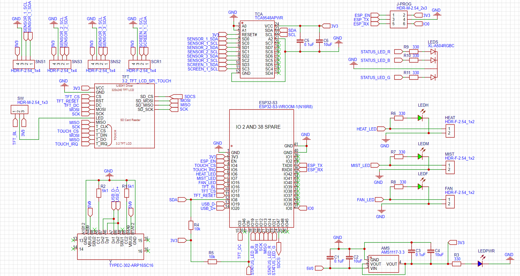
On a brief scan of the schematic the only thing I noticed is that I2C pull up resistors are not shown but if that is a TCA9548 module, these will be present.
EDIT
Where you have headers for HEAT, MIST and FAN is anything connected directly there which could cause a power supply glitch and/or have you noticed a relationship between the crashes and devices being switched on by your circuit ?
0 = reason can not be determined
1 = board power-on
2 = external (pin) reset
3 = software reboot (esp_reset())
4 = exception and/or kernel panic
5 = interrupt watchdog
6 = task watchdog
7 = other watchdog
8 = returning from a deep sleep
9 = brownout (software or hardware)
10 = reset over SDIO
11 = reset by USB peripheral
12 = reset by JTAG
13 = reset due to eFuse error
14 = power glitch detected
15 = CPU lock up (double exception)
Numbers Y and Z (per-core details):
1 =   "Power on reset",
3 =   "Software resets the digital core",
5 =   "Deep sleep resets the digital core",
6 =   "SDIO module resets the digital core",
7 =   "Main watch dog 0 resets digital core",
8 =   "Main watch dog 1 resets digital core",
9 =   "RTC watch dog resets digital core",
11 =  "Main watch dog resets CPU",
12 =  "Software resets CPU",
13 =  "RTC watch dog resets CPU",
14 =  "CPU0 resets CPU1 by DPORT_APPCPU_RESETTING",
15 =  "Reset when the VDD voltage is not stable",
16 =  "RTC watch dog resets digital core and RTC module"
OK. I think I see what you are doing with the TCA9548 but it is really only useful when you have a number of devices with the same I2C address. I don't imagine that the I2C screen (SSD 1306 ?) has the same I2C address as the three sensors so it could be on the main I2C bus. However, that is not the main issue.
If you are using a raw TCA9548APWR chip (as opposed to a module which would have these) then you also need pullup resistors (say 4.7k) on the networks SDA and SCL on your schematic.
The TCA is for the 3 SHT3x modules, they can only be set to one of two addresses so over the top but they are more accurate than BME or SHT2x and not as expensive as the SHT4x is.
They have the pullups on the boards from the headers shown in the schematic. Best practise to put them as close to source as possible, as done with the main SCA SDA lines from the MCU but the board fits behind the ST9976S mounted on the back and really wanted to keep it compact and the tracing was as nightmare adding in the resistors close to the TCA.
I have ordered each part of the board modules (ESP32 socket, power, TCA etc) in that I have cut down to be modular so I can have the whole board as an exploded view once wired. Saying that I have had this working but on perfboard and one long massive .ino, that I wish I kept rather than working on splitting it out for readability.... and a little OSD