Add a series resistor to the Piezo, ~220R.
what for?
A Piezo is similar to a capacitor.
We don't want to place a capacitor on an output pin as it will draw too much current when it charges.
We add a series resistor to limit the output current to a safe level that the output pin can handle.
The buzzer takes in 20ma and the teensy 4.1 pins can handle 250ma max rating.
Show us where an output pin on the teensy can handel 1/4 Amp
I was wrong. Apparently each gpio pin can do 10 ma and 3.3v can do 250ma. I guess I can put a resistor there to ensure it never goes above 20ma. Also, what do you think about my 5v buck circuit? Any issues there?
How much of the schematic have you actually tested to show that it actually works ?
I design PCBs, and I will add bits to a design that I know will work. If there is some component or device in the schematic that is new to me or I am not sure about, I breadbord test it myself first, is that not the normal 'design' process ?
Ive only tested the on and off switch on my old pcb(not very useful) However, I have two teensy 4.1 on the way so i will test the mpu6050 schematic as well as pyro channels.
I cant really test the smd stuff tho
Why not ?
You can get breakout PCBs that allow you to breadboard most SMT stuff.
I could do that but it would take a lot off time
But actually thats a great idea, I will do that
you are talking about these right? Overview | SMT Breadboard Prototyping Using Breakout PCBs | Adafruit Learning System
Here is a simple example.
The Teensy 4.1 can plug into a breadboard, and it would take how long to check that the Teensy pins can drive the buzzer your using effectivly, not long. So did you check ?
I have come across Micros that do not provide enough current to drive a Piezo effectivly, so whilst you might think your designing in a buzzer, your not.
Check, check, check.
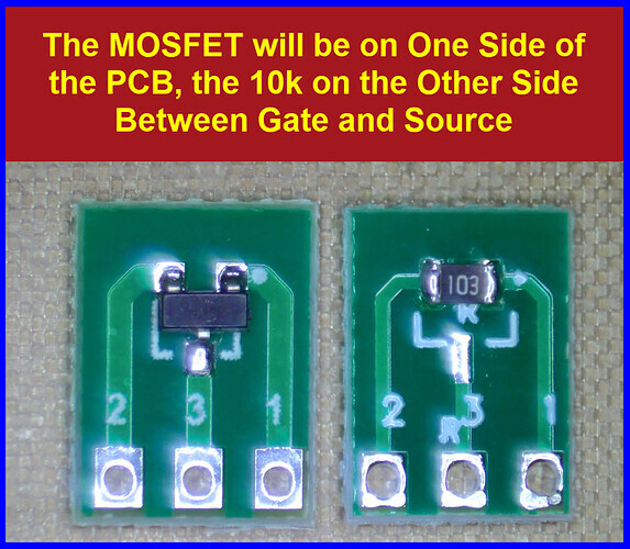


Yes, and you can get them for most of the larger multi pin SMT devices well. Cheap on aliexpress for instance.
Yeah i guess you’re right. Ill just wait until i get the parts to test everything
Good plan.
If a designed PCB or 'checked' schematic does not work, then debugging it can be very difficult indeed.
So I just got two teensy 4.1s and ran some tests. Programming these was so easy, I just used platformio. Then, I got the teensy to run off only a 7.4 lipo fed into a 5v, 1.2amp buck converter. Then, I connected a servo and got it to work perfectly. I also got the mpu6050 and directional cosine matrices to give orientation data. So I can verify that works. The things I dont that if they work are: bmi088, bmp280, 5v buck converter, pyro, and buzzer.

Also, the servos only work with external power. Is there anyway to power the servos directly from usb without using the 3.3v?