Hi Everyone,
I always use this forum to get a peer review. I am slowly expanding my expertise in PCB design. And have tested each component piece by piece. However, I would still appreciate it if you could review the schematic and highlight any shortfalls or issues with the design.
@jim-p@6v6gt - you guys have helped me in the past. A big shoutout to you for helping again.
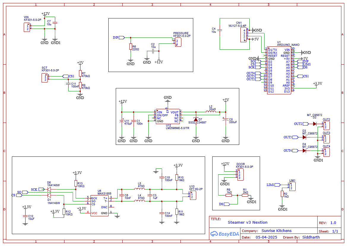
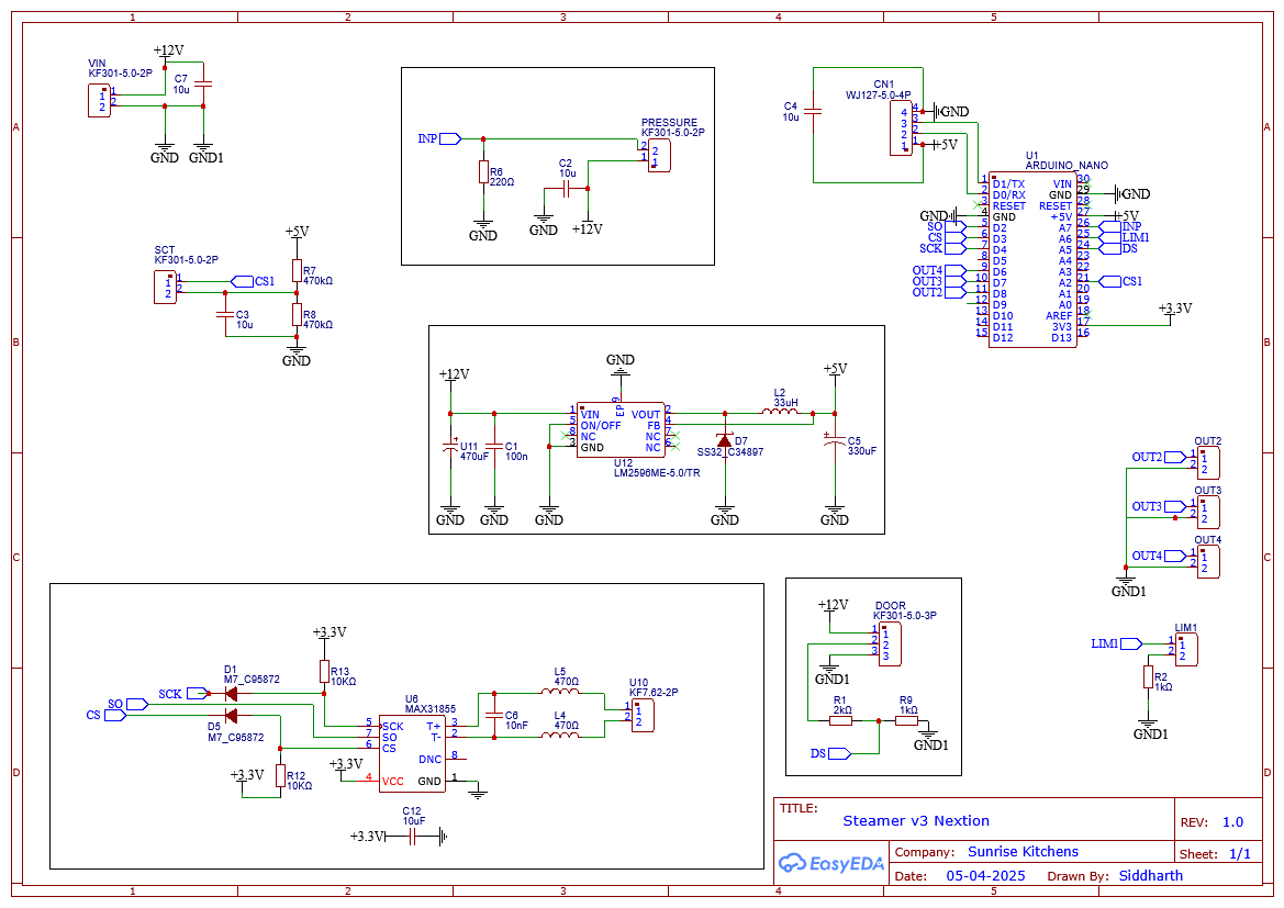
VIN - used to connect the output from a 12V DC SMPS
SCT is used to connect to SCT-013-030 Non-invasive AC Current Sensor Clamp Sensor
The voltage divider at DS looks inverted. Anyway, ensure it delivers no more than 5v to pin A5.
Try to keep pins A4 and A5 free in case you want later to add an I2C device.
Use Schottky diodes for D1 and D6 instead of the 1N4148 to ensure that the voltage on CS is always in the defined range.
R10, R11, C14, C15 and C3 - these were not recommended in the manual. After your post, I believe I may have overevaluated it. Pull-up resistors are added to reduce noise and improve accuracy.
Door Sensor - Re-evaluating it. Let me come back to this.
One question: Am I right in connecting the 3.3V output from the Arduino to power the MAX31855?
What does "majority" mean?
Do you consider your design to be in the majority?
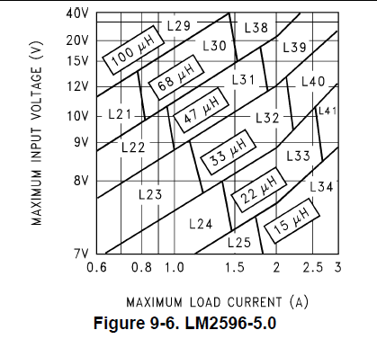
What is the minimum and maximum current your system will need?
C6 is recommended in the manual
Looking at the most recent datasheet, I see no mention of putting a 0.1uF cap across the thermocouple lines.
I suggest you download the latest datasheet and carefully read the application information section. Do as they recommend.
Pull-up resistors are added to reduce noise and improve accuracy.
They could damage the IC, will probably add noise and will certainly keep the automatic fault detection from working. Remove R10, R11, C14, C15 and C3.
Door Sensor - Re-evaluating it. Let me come back to this.
If you have it , measure the resistance between the brown and black wires.
One question: Am I right in connecting the 3.3V output from the Arduino to power the MAX31855?
Well let's find out.
How much current can the nano 3.3V supply?
Is the 3.3V supply from the nano well regulated?
How much current does the MAX31855 need?
I would make C11 10uF.
What is the purpose of D2, D23 and D4?
Arduino nano 3.3V max output 50mA. And the output is regulated.
MAX31855 consumption is just 1.5mA
Door Sensor
The resistance between the brown and black wires is 2.5 ohms
Voltage at DS 1/3 x 12V = 4V (approx)
Removed R10, R11, C14, C15 and C3
MAX31855 Datasheet
From the datasheet
"Noise Considerations
Because of the small signal levels involved, thermocouple temperature measurement is susceptible to powersupply coupled noise. The effects of power-supply noise can be minimized by placing a 0.1μF ceramic bypass capacitor close to the VCC pin of the device and to GND.
The input amplifier is a low-noise amplifier designed to enable high-precision input sensing. Keep the thermocouple and connecting wires away from electrical noise sources. It is strongly recommended to add a 10nF ceramic surface-mount differential capacitor, placed across the T+ and T- pins, in order to filter noise on the thermocouple lines."