Hi there,
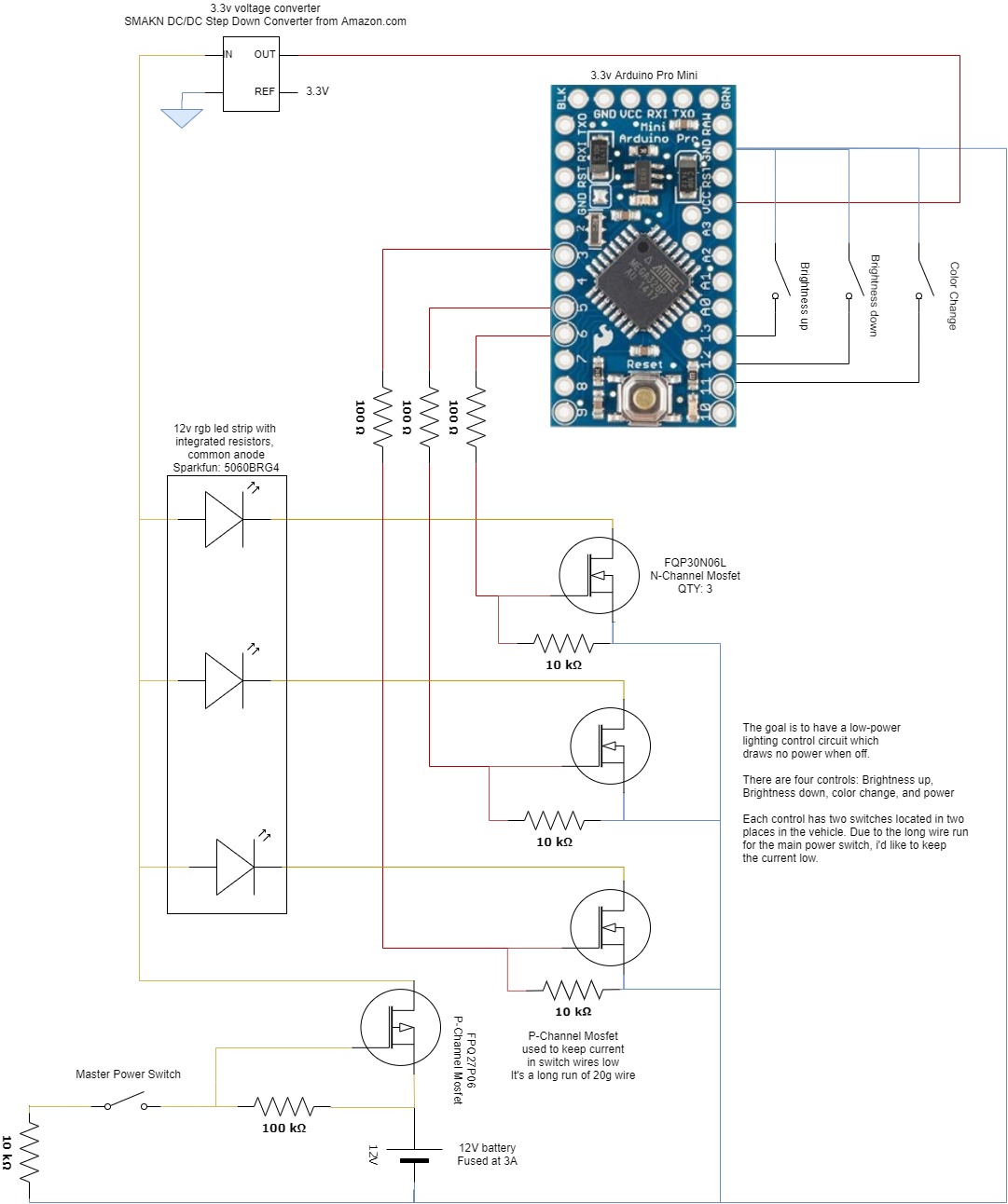
This is my first post--i'm new to circuit design and the forum. I'm working on a project for a battery-powered 12V LED controller that allows users to dim and change the color of an RGB LED. I'd like the entire circuit to have a hardware power switch that kills power to both the LEDs and the Arduino controller. The wiring running to the switches is to thin to carry the full load of the circuit, so i'm using a P-Channel Mosfet as the power switch. I'm new to this and don't know if it will work in the current setup. Is there anyone here who'd be willing to take a look at my attached schematic and let me know if they see any errors? Thanks a bunch!

The LED strip referred to as common Cathode is drawn as common Anode.
The LED mosfet gates do not need 10k resistors to the output pins, 100 ohm would suffice. However, run the existing 10k to ground from the gate to make sure gate does not float.
Pull-up resistors can be quite simply programmed in with the code doing away with the pull down resistors shown.
There is no requirement to show the push button double pole arrangement in your drawings even if that is the basic structure of the tactile switch you intend to use.
Don't forget to use some form of switch debounce in your code.
Top marks for NOT using fritzing and for basic schematic layout.....not bad for first go ![]()
![]()
bluejets:
The LED strip referred to as common Cathode is drawn as common Anode.The LED mosfet gates do not need 10k resistors to the output pins, 100 ohm would suffice. However, run the existing 10k to ground from the gate to make sure gate does not float.
Pull-up resistors can be quite simply programmed in with the code doing away with the pull down resistors shown.
There is no requirement to show the push button double pole arrangement in your drawings even if that is the basic structure of the tactile switch you intend to use.Don't forget to use some form of switch debounce in your code.
Top marks for NOT using fritzing and for basic schematic layout.....not bad for first go

Hahaha, I tried Fritzing for all of 2 minutes before I got fed up. Draw.io is a great free tool.
I updated the drawings--is this what you're recommending?
Common Cathode was a typo--now corrected. Have a code debounce--thanks for the heads up.
Does the P-channel main power switch look like it will work?
Thank you for the help!
If you go back to your last post and right click and copy the address of the jpg. you can then go to modify at the lower right and add that image as a url address. This puts the photo in the posting rather than others having to download.
For high side switching.....
I waited to see if you realised the same resistance changes made to the n-channel mosfets could be done with the P-channel but you missed it...... (5% off top mark.... ![]()
![]()
![]() )
)
Wow. I feel dumb. I really did not understand that FETs don't suck up any current and are voltage-driven. The last project I did used BJTs.
What does the 100 ohm resistor do on the LED driver FETs?
Any other protections a good idea? Decoupling caps to protect the Arduino?
Thanks for the help. This has been very informative.

What does the 100 ohm resistor do on the LED driver FETs?
Just in case of any unpredictable problem, it offers some degree of microcontroller pin protection.
BTW, you have eliminated it in the last drawing.
Have used it either way on many occasions without any problem though.
The 10k resistor should not go from the FET gate to ground but from the Arduino output pin to ground, on the other side of the 100 Ohm resistors. Its only purpose is to avoid the LEDs flickering as the Arduino initialises and the pins are floating.
The purpose of the 100 Ohm resistors is to limit the load on the Arduino outputs presented by the gate capacitance of the FETs as the PWM is applied. Charging and discharging that capacitance results in transient high current impulses which would otherwise technically exceed the current ratings of the ATmega output drivers. There is some dispute as to whether this actually matters. ![]()
Hi all,
Thanks again for the help. I just want to give an update for any future readers. I built the circuit as shown in V3 and everything worked fine, except I was getting a 2 hz flicker. After viewing the PWM signals on a scope, I found that pin 5 and pin 6 were a different frequency than pin 3, and the lights flickered when the square waves crossed.
I did some reading and found that pin 5 and 6 are on Timer 0, which has a faster clock speed than the other two timers. Fixed the issue by rewiring the LED control signals to pins controlled by Timer 1 and Timer 2.
These articles helped: