I breadboarded an Auduino, adding AC coupling and a voltage divider to the output, because I'd like to safely play it through my guitar amp.
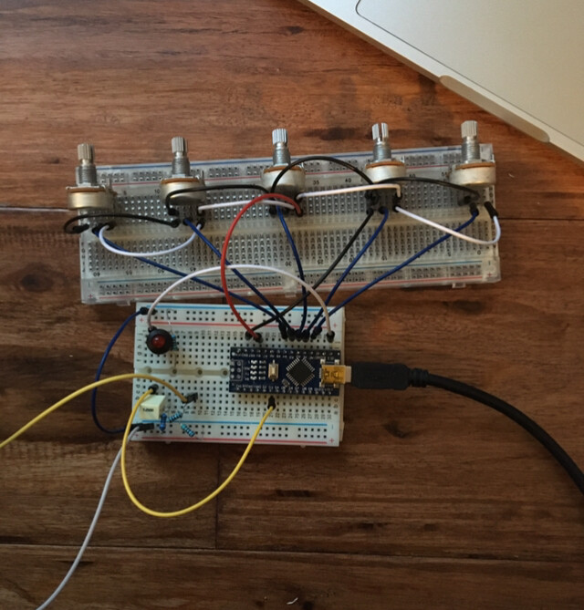
Breadboarded (with an Uno) it sounds great, but when I soldered it all up (with a nano) the output volume is really low. I'm pretty new to electronics - could low volume be due to a bad solder joint? How might I got about troubleshooting this issue? I have a multimeter, but no oscilloscope.
Thanks so much for your time!
Edit: I drew the pots wrong on my original diagram.
Two different breadboards. Do you think it’s possible that the pots burned out while I was testing it on the breadboard? Would that make it quieter? The pots all still affect the sound though…
No.
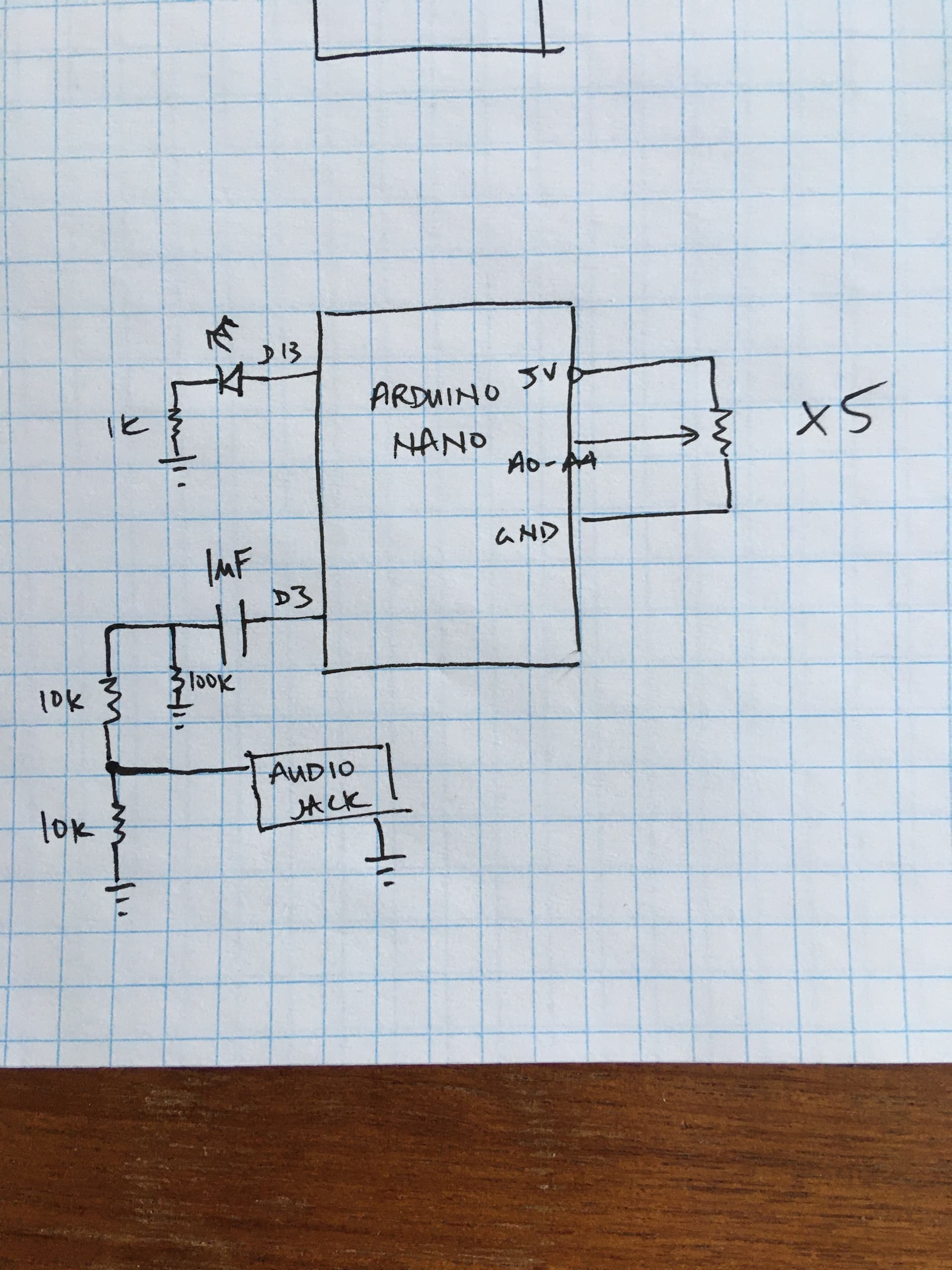
You have shown them on your circuit with the wiper connected to ground and the other end of the pot to 5V.
However this isn’t how you have it in your photograph. You connect the wiper to an analogue input. I suspect this is what you want to do.
A schematic is nothing if it is not accurate. If we can’t trust the simple stuff how can we trust the stuff you are asking about?
Thanks for the corrections.
Now we can concentrate on getting the output correct.
First off remove the 100K to ground resistor. This is acting as a low pass filter and is removing a lot of the high frequency from the output of your synth.
Then remove the 10K to ground, all this does is to cut down the volume of the output.
Try it like that first. The only effect of the series 1K is to increase the input impedance into your amplifier. This is normally something you don't want because this will increase the noise picked up from the digital switching circuits, so you could try removing that as well.