Kai-R
February 23, 2024, 4:06pm
21
Es gibt keinen 3,3V Nano ... Wenn Du den Lüfter mit dem Potentiometer nicht regeln kannst, ist das Potentiometer und/oder der Lüfter falsch angeschlossen.
https://www.intel.com/content/dam/support/us/en/documents/intel-nuc/intel-4wire-pwm-fans-specs.pdf
Die Lüfteranschlüsse:
GND Schwarz
Welche Fehlermeldung kommt denn?
Rentner
February 23, 2024, 4:47pm
22
Serial.println(potiwert) ;
Serial.println(pwmwert);
an geeigneter Stelle wäre da hilfreich
Kai-R
February 23, 2024, 6:24pm
23
Ich habe die Schaltung mal zusammen gesteckt:
Vielleicht hilft das Bild ja weiter...
Wenn man den LDO nicht verwendet, darf die 12V Seite (unten) natürlich nicht mit der 5V Seite (oben) verbunden sein (rote Steckbrücken über dem LDO). Nur Ground muss verbunden sein.
Die Kabel schwarz, gelb, grün und blau sind entsprechend ihrer Farbe mit dem, auf dem Bild nicht sichtbaren, 4-poligen Stecker des Lüfters verbunden.
Die Konsolenausgabe wurde mit Hilfe eines FTDI Adapters (TX Pin vom Nano auf RX Pin des Adapters und GND) ermöglicht. Das ist hier auf dem Bild aber auch nicht abgebildet. Wird der Nano über USB betrieben, braucht man das auch nicht machen.
Das Potentiometer hat 10kΩ ... Das ist auf meinen Plan aus #7 leider nicht eingetragen. Muss ich mal korrigeren.
Kai-R
February 24, 2024, 12:07pm
24
Ich habe das mal mit zwei Lüftern ausprobiert. Funktioniert.
Das Bild ist jetzt nur nicht mehr ganz so übersichtlich wie das erste:
PWM ist parallel angeschlossen. Die Anschlüsse für 12V und Tacho wurden einfach zwei mal (fast) identisch (entsprechend dem Schaltplan #7 ) aufgebaut, wobei der Tachoanschluss von Lüfter Eins an Pin D2, der von Lüfter Zwei an D3 angeschlossen ist.
Der angepasste Quellcode für zwei Lüfter:
#include <Arduino.h>
#include <util/atomic.h>
#include <Streaming.h>
Print &cout = Serial;

#define MAX_FANS 2U  // Define number of fans 1 or 2 !
static_assert(MAX_FANS> 0 && MAX_FANS < 3,"Only 1U or 2U are allowed");

//////////////////////////////////////////////////////////////////////////////
/// @brief Timerclass for millis()
///
//////////////////////////////////////////////////////////////////////////////
class Timer {
public:
  void start() { timeStamp = millis(); }
  bool operator()(const unsigned long duration) const { return (millis() - timeStamp >= duration) ? true : false; }

private:
  unsigned long timeStamp {0};
};


//////////////////////////////////////////////////////////////////////////////
/// @brief Class for calculating a simple average
///
/// @tparam T           Datatype
/// @tparam MAX_SIZE    Maximum number of individual values for calculating the average
//////////////////////////////////////////////////////////////////////////////
template <typename T, uint8_t MAX_SIZE = 1> class Average {
public:
  uint8_t getIdx() { return idx; };

  const void setValue(T val) {
    values[idx] = val;
    if (++idx >= maxIdx) idx = 0;
  }

  T getAverage() {
    T tmp = 0;
    for (auto value : values) { tmp += value; }
    return tmp / maxIdx;
  }

private:
  const uint8_t maxIdx {MAX_SIZE};
  T values[MAX_SIZE];
  uint8_t idx {0};
};

//////////////////////////////////////////////////////////////////////////////
/// @brief Calculates the average rotation frequency of a fan.
///
/// @tparam T         Type
/// @tparam MAX_SIZE  Arraysize
/// @param duration   Time between two edge signals
/// @param readings   Object which is used to calculate the average
/// @return uint32_t  Average value
//////////////////////////////////////////////////////////////////////////////
template <typename T, uint8_t MAX_SIZE = 1> uint32_t calcAvgFrequency(volatile uint32_t &duration, T &readings) {
  uint32_t freq {0};
  if (duration > 0) { freq = 100000000 / duration; }
  readings.setValue(freq);
  return readings.getAverage();
}

//////////////////////////////////////////////////////////////////////////////
/// global constants
///
//////////////////////////////////////////////////////////////////////////////

constexpr uint8_t PIN_ANALOG {A0};

constexpr uint16_t HERTZ {25000};
constexpr uint16_t PRESCALER {1};
constexpr uint8_t CLOCKSET {_BV(CS10)};
constexpr uint16_t ICOUNTER {static_cast<uint16_t>((F_CPU / (2UL * PRESCALER * HERTZ)) - 1)};

constexpr uint16_t INTERVAL_MS {1000};
constexpr uint8_t MAX_AVERAGE_IDX {12};

volatile uint32_t durationInt0;
volatile uint32_t lastDurInt0;

volatile uint32_t durationInt1;
volatile uint32_t lastDurInt1;

//////////////////////////////////////////////////////////////////////////////
/// Global variables / objects
///
//////////////////////////////////////////////////////////////////////////////

Timer timer;
Average<uint32_t, MAX_AVERAGE_IDX> rpmInt[MAX_FANS];

//////////////////////////////////////////////////////////////////////////////
/// @brief Enable external interrupts for INT0 and INT1 Pins (D2, D3)
///
//////////////////////////////////////////////////////////////////////////////
void enableExternalInterrupts() {
  EICRA = _BV(ISC11) | _BV(ISC10) | _BV(ISC01) | _BV(ISC00);   // Int0 & Int1 -> rising edge
  EIMSK = _BV(INT1) | _BV(INT0);
}

// External Interrupt Pin D2
//
//////////////////////////////////////////////////////////////////////////////
/// @brief  To determine the speed, measure the time between the edge changes (rising edge).
///         A fan provides two edge changes per revolution.
//////////////////////////////////////////////////////////////////////////////
ISR(INT0_vect) {
  uint32_t timestamp = micros();
  durationInt0 = (timestamp - lastDurInt0);
  lastDurInt0 = timestamp;
}


// External Interrupt Pin D3 second fan
ISR(INT1_vect) {
  uint32_t timestamp = micros();
  durationInt1 = (timestamp - lastDurInt1);
  lastDurInt1 = timestamp;
}

//////////////////////////////////////////////////////////////////////////////
/// @brief Init PWM signal (25kHz)
///
//////////////////////////////////////////////////////////////////////////////
void pwmInit() {
  DDRB |= _BV(PB1);   // OCR1A Pin (PB1 / D9)
  TCCR1A = _BV(WGM11);
  TCCR1B = _BV(WGM13);
  ATOMIC_BLOCK(ATOMIC_RESTORESTATE) { ICR1 = ICOUNTER; }
}

//////////////////////////////////////////////////////////////////////////////
/// @brief Set dutycycle of the PWM signal
///
/// @param dc   0-100%
//////////////////////////////////////////////////////////////////////////////
void pwmSetDutyCycle(uint8_t dc) {
  uint16_t ocr1a = (dc > 100) ? 100 : dc;
  ocr1a = static_cast<uint16_t>((((ICR1 * 10UL * ocr1a) / 100) + 5) / 10);   // Result must be 16Bit
  ATOMIC_BLOCK(ATOMIC_RESTORESTATE) { OCR1A = ocr1a; }
}

//////////////////////////////////////////////////////////////////////////////
/// @brief start PWM signal
///
//////////////////////////////////////////////////////////////////////////////
void pwmStart() {
  TCCR1A |= _BV(COM1A1);
  TCCR1B |= CLOCKSET;
}

//////////////////////////////////////////////////////////////////////////////
/// @brief stop PWM signal
///
//////////////////////////////////////////////////////////////////////////////
void pwmStop() {
  TCCR1B &= ~(_BV(CS10) | _BV(CS11) | _BV(CS12));
  TCCR1A &= ~(_BV(COM1A1));
  PORTB &= ~(_BV(PB1));   // OCR1A Pin (PB1 / D9) to LOW
}

//////////////////////////////////////////////////////////////////////////////
/// @brief Show Frequency and RPM on the serial console
///
/// @param freq
//////////////////////////////////////////////////////////////////////////////
void showRPM(uint32_t freq, uint8_t fanNr) {
  uint32_t rpm = freq * 60;
  rpm /= 200;
  cout << "Lüfter Nr: " << fanNr << " Frequenz: " << freq / 100 << "." << freq % 100 << "Hz Rpm: " << rpm << endl;
}

//////////////////////////////////////////////////////////////////////////////////////
// Main program
//////////////////////////////////////////////////////////////////////////////////////
void setup(void) {
  Serial.begin(115200);
  enableExternalInterrupts();
  pwmInit();
  pwmSetDutyCycle(100);
  pwmStart();
  delay(10000);   // full speed for 10 seconds

  timer.start();
}

void loop() {
  static uint16_t oldValue {0};
  static uint8_t show[MAX_FANS] {0};
  static uint32_t freq[MAX_FANS] {0};

  // Determine the potentiometer position and set the duty cycle accordingly.
  uint16_t value = map(analogRead(PIN_ANALOG), 0, 1015, 20, 100);
  if (value != oldValue) {
    oldValue = value;
    pwmSetDutyCycle(value);
  }

  // Determine the fan speed and output it via the serial interface.
  // Do this every INTERVAL_MS milliseconds
  if (timer(INTERVAL_MS) == true) {
    timer.start();
    freq[0] = calcAvgFrequency(durationInt0, rpmInt[0]);
#if (MAX_FANS > 1)
    freq[1] = calcAvgFrequency(durationInt1, rpmInt[1]);
    for (uint8_t i = 0; i < MAX_FANS; ++i) {
      if (show[i] < (MAX_AVERAGE_IDX + 1)) {
        ++show[i];
      } else {
        showRPM(freq[i],i);
      }
    }
    cout << endl;
#else
    if (show[0] < (MAX_AVERAGE_IDX + 1)) {
      ++show[0];
    } else {
      showRPM(freq[0],1);
    }
#endif
  }
}
Eine Ausgabe auf ein Display sollte sich da leicht einbauen lassen.
uwefed
February 24, 2024, 7:35pm
25
Auf dem Plan in #16 fehlt die Verbindung zwischen GND der Motorspannung (-12V bzw PNetzteil) und GND des Arduino.
Kai-R
February 25, 2024, 11:12am
26
Die Lüftersteuerung mit LCD Anzeige:
Der Code:
//////////////////////////////////////////////////////////////////////////////
/// @brief Example program
/////////////////////////////////////////////////////////////////////////////////
/// @file main.cpp
/// @author Kai R. ()
/// @brief  PWM Fan control - Suitable for microcontroller boards based on the ATMega328.
///
/// @date 2024-02-25
/// @version 1.0
///
//////////////////////////////////////////////////////////////////////////////

#include <Arduino.h>
#include <Streaming.h>           // https://github.com/janelia-arduino/Streaming
#include <LiquidCrystal_I2C.h>   // https://github.com/johnrickman/LiquidCrystal_I2C
#include <util/atomic.h>

//////////////////////////////////////////////////////////////////////////////
/// global definitions / constants
///
//////////////////////////////////////////////////////////////////////////////

// #define SERIALOUT
#ifdef SERIALOUT
Print &cout = Serial;
#endif

#define MAX_FANS 2U   // Define number of fans 1 or 2 !
static_assert(MAX_FANS > 0 && MAX_FANS < 3, "Only 1U or 2U are allowed");

constexpr uint8_t PIN_ANALOG {A0};

// Values for generating the PWM signal
constexpr uint16_t HERTZ {25000};
constexpr uint16_t PRESCALER {1};
constexpr uint8_t CLOCKSET {_BV(CS10)};
constexpr uint16_t ICOUNTER {static_cast<uint16_t>((F_CPU / (2UL * PRESCALER * HERTZ)) - 1)};

// Timeconstants
constexpr uint16_t INTERVAL_MS {1000};
constexpr uint16_t STARTUP_TIME_SEC {10};

constexpr uint8_t MAX_AVERAGE_IDX {12};   // Number of array elements for calculating the average

// LCD values
constexpr uint8_t LCD_LINES {4};   // Set 2 for 2x16 Display, 4 for 4x20 Display
constexpr uint8_t LCD_COLONS {(LCD_LINES == 2) ? 16 : 20};
constexpr uint8_t SECOND_LINE {(LCD_LINES == 2) ? 1 : 2};
constexpr uint8_t LEFT_COL {(LCD_LINES == 2) ? 0 : 2};
constexpr uint8_t LEFT_COL_CNTDWN {(LCD_LINES == 2) ? 2 : 4};
constexpr uint8_t DATA_DIGITS {5};
constexpr uint8_t DATA_WIDTH {DATA_DIGITS + 2};
constexpr uint8_t DATA_COL {LEFT_COL + DATA_DIGITS + 1};
constexpr uint8_t CNTDWN_BAR {10};
constexpr uint8_t CNTDWN_CHAR {'*'};

//////////////////////////////////////////////////////////////////////////////
/// @brief Timerclass for millis()
///
//////////////////////////////////////////////////////////////////////////////
class Timer {
public:
  void start() { timeStamp = millis(); }
  bool operator()(const unsigned long duration) const { return (millis() - timeStamp >= duration) ? true : false; }

private:
  unsigned long timeStamp {0};
};

//////////////////////////////////////////////////////////////////////////////
/// @brief Class for calculating a simple average
///
/// @tparam T           Datatype
/// @tparam MAX_SIZE    Maximum number of individual values for calculating the average
//////////////////////////////////////////////////////////////////////////////
template <typename T, uint8_t MAX_SIZE = 1> class Average {
public:
  uint8_t getIdx() { return idx; };

  const void setValue(T val) {
    values[idx] = val;
    if (++idx >= maxIdx) {   // array is filled
      divideByMaxIdx = true;
      idx = 0;
    }
  }

  T getAverage() {
    T tmp = 0;
    for (auto value : values) { tmp += value; }
    // Only divide by the total number of array elements
    // once the array has been completely filled with measured values.
    return (divideByMaxIdx == true) ? tmp / maxIdx : tmp / idx;
  }

private:
  const uint8_t maxIdx {MAX_SIZE};
  T values[MAX_SIZE] {0};
  uint8_t idx {0};
  bool divideByMaxIdx {false};
};

//////////////////////////////////////////////////////////////////////////////
/// @brief Calculates the average rotation frequency of a fan.
///
/// @tparam T         Type
/// @tparam MAX_SIZE  Arraysize
/// @param duration   Time between two edge signals
/// @param readings   Object which is used to calculate the average
/// @return uint32_t  Average value
//////////////////////////////////////////////////////////////////////////////
template <typename T, uint8_t MAX_SIZE = 1> uint32_t calcAvgFrequency(volatile uint32_t &duration, T &readings) {
  uint32_t freq {0};
  if (duration > 0) { freq = 100000000 / duration; }
  readings.setValue(freq);
  return readings.getAverage();
}

//////////////////////////////////////////////////////////////////////////////
/// Global variables / objects
///
//////////////////////////////////////////////////////////////////////////////

// used by interrupt routine(s)
volatile uint32_t durationInt0;
volatile uint32_t lastDurInt0;

volatile uint32_t durationInt1;
volatile uint32_t lastDurInt1;

Timer timer;
Average<uint32_t, MAX_AVERAGE_IDX> rpmInt[MAX_FANS];
// LiquidCrystal_I2C lcd(0x27, LCD_COLONS, LCD_LINES);   // I2C Addr 2x16
LiquidCrystal_I2C lcd(0x3F, LCD_COLONS, LCD_LINES);   // I2C Addr 4x20
Print &coutLcd = lcd;

//////////////////////////////////////////////////////////////////////////////
/// @brief Enable external interrupts for INT0 and INT1 Pins (D2, D3)
///
//////////////////////////////////////////////////////////////////////////////
void enableExternalInterrupts() {
  EICRA = _BV(ISC11) | _BV(ISC10) | _BV(ISC01) | _BV(ISC00);   // Int0 & Int1 -> rising edge
  EIMSK = _BV(INT1) | _BV(INT0);
}

// External Interrupt Pin D2
//
//////////////////////////////////////////////////////////////////////////////
/// @brief  To determine the speed, measure the time between the edge changes (rising edge).
///         A fan provides two edge changes per revolution.
//////////////////////////////////////////////////////////////////////////////
ISR(INT0_vect) {
  uint32_t timestamp = micros();
  durationInt0 = (timestamp - lastDurInt0);
  lastDurInt0 = timestamp;
}

// External Interrupt Pin D3, second fan
ISR(INT1_vect) {
  uint32_t timestamp = micros();
  durationInt1 = (timestamp - lastDurInt1);
  lastDurInt1 = timestamp;
}

//////////////////////////////////////////////////////////////////////////////
/// @brief Init PWM signal (25kHz)
///
//////////////////////////////////////////////////////////////////////////////
void pwmInit() {
  DDRB |= _BV(PB1);   // OCR1A Pin (PB1 / D9)
  TCCR1A = _BV(WGM11);
  TCCR1B = _BV(WGM13);
  ATOMIC_BLOCK(ATOMIC_RESTORESTATE) { ICR1 = ICOUNTER; }
}

//////////////////////////////////////////////////////////////////////////////
/// @brief Set dutycycle of the PWM signal
///
/// @param dc   0-100%
//////////////////////////////////////////////////////////////////////////////
void pwmSetDutyCycle(uint8_t dc) {
  uint16_t ocr1a = (dc > 100) ? 100 : dc;
  ocr1a = static_cast<uint16_t>((((ICR1 * 10UL * ocr1a) / 100) + 5) / 10);   // Result must be 16Bit
  ATOMIC_BLOCK(ATOMIC_RESTORESTATE) { OCR1A = ocr1a; }
}

//////////////////////////////////////////////////////////////////////////////
/// @brief start PWM signal
///
//////////////////////////////////////////////////////////////////////////////
void pwmStart() {
  TCCR1A |= _BV(COM1A1);
  TCCR1B |= CLOCKSET;
}

//////////////////////////////////////////////////////////////////////////////
/// @brief stop PWM signal
///
//////////////////////////////////////////////////////////////////////////////
void pwmStop() {
  TCCR1B &= ~(_BV(CS10) | _BV(CS11) | _BV(CS12));
  TCCR1A &= ~(_BV(COM1A1));
  PORTB &= ~(_BV(PB1));   // OCR1A Pin (PB1 / D9) to LOW
}

//////////////////////////////////////////////////////////////////////////////
/// @brief Show Frequency and RPM on the serial console
///
/// @param freq
//////////////////////////////////////////////////////////////////////////////
#ifdef SERIALOUT
void showRPM(uint32_t freq, uint8_t fanNr) {
  uint32_t rpm = freq * 60;
  rpm /= 200;
  cout << "Lüfter Nr: " << fanNr << " Frequenz: " << freq / 100 << "." << freq % 100 << "Hz Rpm: " << rpm << endl;
}
#endif

//////////////////////////////////////////////////////////////////////////////
/// @brief Show start sequence on LCD
///
//////////////////////////////////////////////////////////////////////////////
void lcdCountDown() {
  uint8_t counter {STARTUP_TIME_SEC};
  lcd.setCursor(LEFT_COL_CNTDWN, 0);
  coutLcd << F("Start up: ") << STARTUP_TIME_SEC;
  lcd.setCursor(LEFT_COL_CNTDWN, SECOND_LINE);
  coutLcd << "[" << _PAD(CNTDWN_BAR, ' ') << "]";
  timer.start();
  do {
    if (timer(INTERVAL_MS) == true) {
      timer.start();
      lcd.setCursor(LEFT_COL_CNTDWN + CNTDWN_BAR, 0);
      coutLcd << _FMT(("%"), _WIDTH(--counter, 2));
      lcd.setCursor(LEFT_COL_CNTDWN + 1, SECOND_LINE);
      coutLcd << _PAD(CNTDWN_BAR - counter, CNTDWN_CHAR);
    }
  } while (counter > 0);
  delay(1000);
}

//////////////////////////////////////////////////////////////////////////////
/// @brief Display the main output text
///
//////////////////////////////////////////////////////////////////////////////
void lcdMain() {
  lcd.clear();
  lcd.setCursor(LEFT_COL, 0);
  coutLcd << "FAN 1:" << _PAD(DATA_WIDTH, ' ') << "RPM";
#if (MAX_FANS > 1U)
  lcd.setCursor(LEFT_COL, SECOND_LINE);
  coutLcd << "FAN 2:" << _PAD(DATA_WIDTH, ' ') << "RPM";
#endif
}

//////////////////////////////////////////////////////////////////////////////
/// @brief Display the RPM
///
/// @param freq
/// @param fanNr
//////////////////////////////////////////////////////////////////////////////
void lcdData(uint32_t freq, uint8_t fanNr) {
#if (MAX_FANS > 1U)
  uint8_t lcdLine = (fanNr == 0) ? 0 : SECOND_LINE;
#else
  uint8_t lcdLine {0};
#endif
  uint32_t rpm = freq * 60;
  rpm /= 200;
  lcd.setCursor(DATA_COL, lcdLine);
  coutLcd << _FMT(("%"), _WIDTH(rpm, DATA_WIDTH - 1));
}

//////////////////////////////////////////////////////////////////////////////////////
// Main program
//////////////////////////////////////////////////////////////////////////////////////
void setup(void) {
#ifdef SERIALOUT
  Serial.begin(115200);
#endif
  lcd.init();
  lcd.backlight();
  enableExternalInterrupts();
  pwmInit();
  pwmSetDutyCycle(100);
  pwmStart();
  lcdCountDown();
  lcdMain();
  timer.start();
}

void loop() {
  static uint16_t oldValue {0};
  static uint32_t freq[MAX_FANS] {0};

  // Determine the potentiometer position and set the duty cycle accordingly.
  uint16_t value = map(analogRead(PIN_ANALOG), 0, 1015, 20, 100);
  if (value != oldValue) {
    oldValue = value;
    pwmSetDutyCycle(value);
  }

  // Determine the fan speed and output it via the serial interface / LCD.
  // Do this every INTERVAL_MS milliseconds
  if (timer(INTERVAL_MS) == true) {
    timer.start();
    freq[0] = calcAvgFrequency(durationInt0, rpmInt[0]);
#if (MAX_FANS > 1U)
    freq[1] = calcAvgFrequency(durationInt1, rpmInt[1]);
    for (uint8_t i = 0; i < MAX_FANS; ++i) {
  #ifdef SERIALOUT
      showRPM(freq[i], i);
  #endif
      lcdData(freq[i], i);
    }
  #ifdef SERIALOUT
    cout << endl;
  #endif
#else
  #ifdef SERIALOUT
    showRPM(freq[0], 0);
  #endif
    lcdData(freq[0], 0);
#endif
  }
}
fs5490
February 25, 2024, 3:34pm
27
vielen dank für die hilfe. habs mit dem alten sketch zum laufen gekriegt, hab die ground verbindung vergessen, wie hier geschrieben wurde. bestell mir jetzt den i2c adapter und bessere lüfter und dann test ichs nochmal. genial, danke
das einzige was noch nicht klappt ist das ganze mit dem nano zu machen. kommt die folgende fehlermeldung
C:\Users\Manfred\AppData\Local\Temp.arduinoIDE-unsaved2024125-7456-1aa2u7r.rlxu\sketch_feb25a\sketch_feb25a.ino:16:10: fatal error: util/atomic.h: No such file or directory#include <util/atomic.h>
Compilation error: util/atomic.h: No such file or directory
oder liegt das am board, denn das hat keinen 5v anschluss
Kai-R
February 25, 2024, 4:44pm
28
Mit der Spannung hat das nichts zu tun. Aber ein ESP32-S3 ist kein ATMega328 μController. Das was Du da zeigst ist ein Nano ESP32 und kein Nano .
fs5490
March 1, 2024, 2:53pm
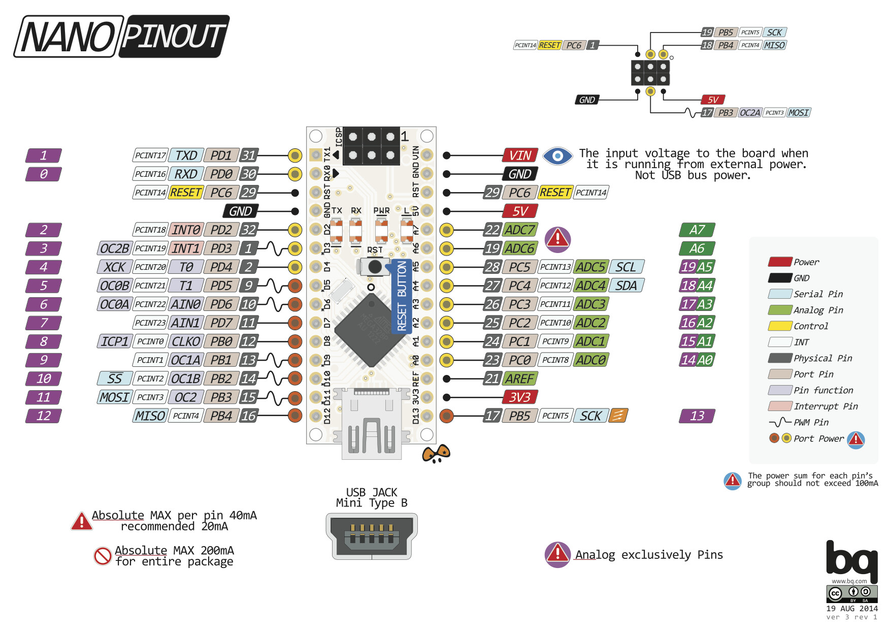
29
ist das display sda an a1 und scl a2 angeschlossen? sehs kaum. und im code muss ich von bei lcd lines von 4 auf 2 bei dem 16x2 display oder? hab mir jetzt noch ein paar dinge gekauft und versuchs mal. vielen dank für deine hilfe, ich wär aufgeschmissen gewesen ohne.
Kai-R
March 1, 2024, 3:57pm
30
Reden wir jetzt von einem Arduino Nano mit ATMega328 Controller?
Gemäß dem Pinout ist das Display an A5 (SCL) und A4 (SDA) angeschlossen. Wenn Du ein 16x2 Display hast, musst Du natürlich die Zeilenzahl auf zwei stellen. Außerdem das LCD Objekt anders initialisieren. In obigem Quellcode ist die Zeile für ein 16x2 auskommentiert. Das musst Du dann ändern.
fs5490
March 1, 2024, 4:23pm
31
ja ist ein nano diesmal.
Kai-R
March 1, 2024, 4:40pm
32
Im Quellcode im Bereich "Global variables / objects" gibt es folgende Zeilen:
// LiquidCrystal_I2C lcd(0x27, LCD_COLONS, LCD_LINES);   // I2C Addr 2x16
LiquidCrystal_I2C lcd(0x3F, LCD_COLONS, LCD_LINES);   // I2C Addr 4x20
Das musst Du "herumdrehen":
LiquidCrystal_I2C lcd(0x27, LCD_COLONS, LCD_LINES);   // I2C Addr 2x16
// LiquidCrystal_I2C lcd(0x3F, LCD_COLONS, LCD_LINES);   // I2C Addr 4x20
Meistens ist die I2C Adresse der 16x2 Displays die 0x27. Aber das muss nicht immer so sein.
uwefed
March 1, 2024, 11:24pm
33
fs5490:
dem nano zu machen
Auf dem Foto in #27 ist kein NANO mit ATmega328, sondern ein anderes Model mit ESP32.
Die Fehlermeldung besagt daß die Bibliothek nicht gefunden wurde.
Grüße Uwe
system
August 28, 2024, 11:25pm
34
This topic was automatically closed 180 days after the last reply. New replies are no longer allowed.