Hey guys,
My Intro to Electricity (Circuits) Professor put us in groups "based on brainpower" so that each group would be fair. Basically this means, all the stupid people get put with the smart people. I've done good on all the exams so far and now I have the sole responsibility of doing everything for my group takehome project. They didn't even know how to do a voltage divider with 2 resistors... >:(
We need to make a simple square wave generator in order to make an LED attached to the output flash on and off. I've tried building several circuits already but the LED has not blinked at all, it will either stay at a constant voltage or dim and turn off completely.
I have LM358N, MC1458N, LM3914N, TL074CN, LM3046N, LM3915N,and LM565CN opamps.
It's required to have atleast one opamp and capacitor. I know this is a fairly simple thing to do, but all the diagrams I can find online are using opamps that aren't in the list above of one's I have.
You need to learn google-ease first - all the answers you'll ever need are there for the asking - though you might have to do some thinking as well. School projects are meant to exercise your brain, not your asking powers
mbferguson:
but all the diagrams I can find online are using opamps that aren't in the list above of one's I have.
Why do you think that matters?
I've succesefully made the opamp with a blinking LED light using this circuit.
https://www.google.com/url?sa=i&rct=j&q=&esrc=s&source=images&cd=&cad=rja&uact=8&ved=0ahUKEwib2Y6spZvTAhXr6oMKHbZBDZAQjRwIBw&url=http%3A%2F%2Fwww.ti.com%2Fproduct%2FLM358-N%2Fdatasheet%2Fapplication_and_implementation&psig=AFQjCNHqHLLgy_Q0xLRUohECWI-73T1mZQ&ust=1491961903734070
Can someone give me a hint on how I would go about making alternating flashing LEDs? As in when one LED is turned off, the other turns on. I'm testing out a capacitor in between two LEDs attached to the output now.
mbferguson:
Can someone give me a hint on how I would go about making alternating flashing LEDs? As in when one LED is turned off, the other turns on. I'm testing out a capacitor in between two LEDs attached to the output now.
Here's your requested hint:
A fundamental op-amp building block, probably the easiest to implement, is the inverter (inverting amplifier).
mbferguson:
I have LM358N, MC1458N, LM3914N, TL074CN, LM3046N, LM3915N,and LM565CN opamps.
LM3914 and LM3915 and are Dot/Bar ("voltmeter") drivers.
I figured it out! All by myself too!!!
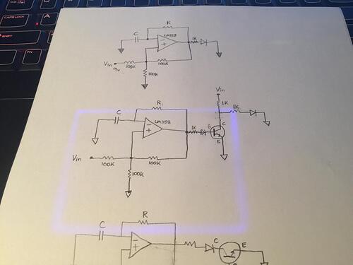
Here is my circuit. I'm not 100% certain why this works, and I'd like it if someone could explain this for me. I expected the LED attached to the C terminal of the transistor to act a bit differently. I initially started with a large 100K resistor to the left of the C LED, thinking that when the blue LED had voltage, it would activate the transistor, and current would pass through the C terminal, and when that would happen there would be no voltage drop across the 100K resistor for the C LED to light up, as all the current is passing through the transistor as opposed to crossing the 100K resistor. However, even when this resistor value next to the C LED is very low, only 1K, the C LED still turns off when the B LED turns on.
The reason I am confused is because I expected some portion of the current to still pass through the C LED, but apparently it all flows down to ground without exception?
Diodes (including LEDs) have some "forward voltage" (value depends on type). Apply less voltage and no current flows through it. Apply more and nearly unlimited current flows (until the diode or power source dies). It is reason why limiting resistors are needed.
(It is a bit more complicated but it is nearly true and explanation of your problem).
