Many LEDs into one Sensor

Hi all,

I am trying to make a touch LED dance floor and I need to connect each tile (20 LEDs) and its respective sensor (IR sensor). I want to map them also into coordinates (x and y), so I can make animations, games, etc. I saw on the internet some touch LED tables and they all do it but each sensor per LED. I want to increase that into one sensor and 20 LEDs, link them, etc.
I cannot find the right code to do it.

Has anyone tried to do something similar?

Thank you

Best regards

Show how you propose to use one sensor. I think you will need 5 x 4 = 20.

I wanna display some light patterns in the tiles of the floor. If the title is a green tile and a person touches the sensor attached to it, it should mark as point 1. if a person touches a red tile then it should remote that point. The detail is that each tile has 20 LEDs and each tile is one sensor.

When you design a project, think also of the physical (will it hold a human or a cup?) and mechanical parts, because all your project parts need to fit somewhere with power. The code will be the fun part. The devices you have or choose will determine the code to write. Can you draw a picture and make a list of the parts you want to use?

Please see the schematics:

1 to 160 would be RGB LEDs, every tile should have a 20-LED strip, but they are all connected into one single strip (160-strip).

Every tile has an IR sensor, they are all connected to arduino separately.

I want to address LEDs 1-20 to Sensor 1, 21-40 to Sensor 2, etc.. and have them all in a XY matrix.

So, whenever I address X=1 to turn red, should turn all 1-20 LEDs to red.
But, If I sensor 1 is pressed or will be pressed, then turn tile 1 (1-20 LEDS) to blue.

This should happen to all 8 tiles independently.

I saw on internet some coffee tables doing that, but they connect only one LED to a sensor. I want to connect 20 LEDs to a sensor.

Tks

If your strips are addressable strips, you can "split" them in software. If something happens on sensor 1, you can update LEDs 1 to 20, if something happens on sensor 2, update LEDs 21 to 40 etc.

The problem is not splitting the strip and request the LEDs to turn on everytime something happens to that particular sensor, but link the group of LEDs to a sensor in a single xy matrix.

So everytime I call some coordinates, I should turn on those LEDs in that coordinate and listen for a response from the sensor of that same xy coordinates.

I wanna use a xy matrix because I can do some loops turning on columns and rows for interactions.

You can use a simulator (link) to begin your project.

Good simulator! but I'm still struggling with the coding

As @sterretje said, you can split the LEDs into groups. The sim loosely represents your drawing (I could not make the rings into squares).

I updated the sim to only color in groups by picking a random group. Now, work on a sensor to make the group selection...

@xfpd, thanks for the simulator!

I already have the strips and sensors in place. My question is for making it into a matrix, link them all together and run interactions

1 Like

Is your IR sensor a PIR? If so, have you tried any example sketches to make one work?
Here is a good example page/video/sketch for the PIR (if that is what you are using):

No, it is an IR sensor.

I connected it to an arduino and made it control a set of LEDs (1-20), so when I press the sensor, they turn on no problem. In fact, I did it with a few sensors and the sequence of LEDs of the strip already.
However, I don't know how to make it a matrix map of the groups of LEDs and link them to the sensors as I described above.

Next step is to make your sketch turn on/off just one set of LEDs in the sim. You can try it on your copy of the sim, and if you post your code here, I will try it on my sim copy. The PIR sensor is the only proximity sensor that the sim has, but it works with +V, GND and SIG, like your IR sensor.

The diagram in post #5 has something missing. Each LED has got only one number. If these were being mapped from a matrix then each LED requires two numbers, the X & Y address of the matrix you need to light that LED.

Once you sort that out you can do the mapping using a lookup table to put them where you want.

Guys,

I tried to get only one tile for example in the picture so you can get it.

@Grumpy_Mike, I don't see any advantage of addressing each LED with and x and y coordinate. I want to group them in groups of 20 LEDs and them give all of them one coordinate x and y, if possible.

@xfpd

I did a small code so far and tried to simulate, somehow it is not working in the simulator. But my code connected to my arduino works. I guess you can understand what I did until now.

Still struggling how to manage to link sensors and LEDs in different matrices.

Code:

#include <Adafruit_NeoPixel.h>
#define LED_PIN 6 // LEDs
#define LED_PIN1 12 // Connected to sensor 1
#define LED_PIN2 11 // Connected to sensor 2
#define LED_PIN3 10 // Connected to sensor 3
#define LED_PIN4 9 // Connected to sensor 4
#define LED_PIN5 8 // Connected to sensor 5
#define LED_PIN6 7 // Connected to sensor 6
#define LED_PIN7 5 // Connected to sensor 7
#define LED_PIN8 4 // Connected to sensor 8

#define LED_NUM 160
Adafruit_NeoPixel strip = Adafruit_NeoPixel(LED_NUM, LED_PIN, NEO_GRB + NEO_KHZ800);

int LEDs[8][20]={{0,1,2,3,4,5,6,7,8,9,10,11,12,13,14,15,16,17,18,19},{20,21,22,23,24,25,26,27,28,29,30,31,32,33,34,35,36,37,38,39},{40,41,42,43,44,45,46,47,48,49,50,51,52,53,54,55,56,57,58,59},{60,61,62,63,64,65,66,67,68,69,70,71,72,73,74,75,76,77,78,79}}
// split all the LEDs into small strips
;
void setup() {
strip.begin(); // initialize the strip
strip.show();
}

void loop()
{

for (int i = 0; i < 20; i++)
{
strip.setPixelColor(LEDs [0][i], strip.Color(255, 255, 0));
strip.show();
}
delay(1000);

// turn on first strip.

if (LED_PIN1 == LOW){
 for (int i = 0; i < 20; i++)
strip.setPixelColor(LEDs [0][i], strip.Color(0, 0, 0));

strip.show();

// turn off first strip

delay(1000);
}}

Simulator file:

dancefloor (1).zip (4.7 KB)

I thought you were using NeoPixels. Oops.
I will look at this. I just started adding sensors to the sim.

1 Like

You can try the following

#define NUMELEMENTS(x) (sizeof(x) / sizeof(x[0]))
#define SENSORACTIVE HIGH

#include <Adafruit_NeoPixel.h>
#define LED_PIN 6    // LEDs
#define LED_PIN1 12  // Connected to sensor 1
#define LED_PIN2 11  // Connected to sensor 2
#define LED_PIN3 10  // Connected to sensor 3
#define LED_PIN4 9   // Connected to sensor 4
#define LED_PIN5 8   // Connected to sensor 5
#define LED_PIN6 7   // Connected to sensor 6
#define LED_PIN7 5   // Connected to sensor 7
#define LED_PIN8 4   // Connected to sensor 8

#define LED_NUM 160
Adafruit_NeoPixel strip = Adafruit_NeoPixel(LED_NUM, LED_PIN, NEO_GRB + NEO_KHZ800);

struct PANEL
{
  const uint8_t sensorPin;  // the sensor pin
  uint8_t sensorStatus;     // status of the sensor
  uint16_t firstLed;        // first led of panel
  uint16_t lastLed;         // last led of panel
};

PANEL panels[2][4] = {
  {
    {12, !SENSORACTIVE, 0, 19},
    {11, !SENSORACTIVE, 20, 39},
    {10, !SENSORACTIVE, 40, 59},
    {9, !SENSORACTIVE, 60, 79},
  },
  {
    {8, !SENSORACTIVE, 80, 99},
    {7, !SENSORACTIVE, 100, 119},
    {5, !SENSORACTIVE, 120, 139},
    {4, !SENSORACTIVE, 140, 159},
  },
};


void setup()
{
  Serial.begin(115200);
  Serial.print(F("Number of panel rows = "));
  Serial.println(NUMELEMENTS(panels));
  Serial.print(F("Number of panels in row = "));
  Serial.println(NUMELEMENTS(panels[0]));

  for (uint8_t yCnt = 0; yCnt < NUMELEMENTS(panels); yCnt++)
  {
    for (uint8_t xCnt = 0; xCnt < NUMELEMENTS(panels[yCnt]); xCnt++)
    {
      Serial.print(F("Setting sensor pin "));
      Serial.print(panels[yCnt][xCnt].sensorPin);
      Serial.println(F(" to input"));
      pinMode(panels[yCnt][xCnt].sensorPin, INPUT);
    }
  }

  strip.begin();  // initialize the strip
  strip.show();
}

void loop()
{
  static uint8_t xCnt, yCnt;

  Serial.print(F("Processing panels["));
  Serial.print(yCnt);
  Serial.print(F("]["));
  Serial.print(xCnt);
  Serial.println(F("]"));

  // read sensor
  uint8_t sensorStatus = digitalRead(panels[yCnt][xCnt].sensorPin);

  // state change
  if (sensorStatus != panels[yCnt][xCnt].sensorStatus)
  {
    // remember state of sensor
    panels[yCnt][xCnt].sensorStatus = sensorStatus;

    if (panels[yCnt][xCnt].sensorStatus == SENSORACTIVE)
    {
      for (uint16_t ledCnt = panels[yCnt][xCnt].firstLed; ledCnt <= panels[yCnt][xCnt].lastLed; ledCnt++)
      {
        // set a colour
        strip.setPixelColor(ledCnt, strip.Color(255, 255, 0));
      }
    }
    else
    {
      // panel off
      for (uint16_t ledCnt = panels[yCnt][xCnt].firstLed; ledCnt <= panels[yCnt][xCnt].lastLed; ledCnt++)
      {
        // set a colour
        strip.setPixelColor(ledCnt, strip.Color(0, 0, 0));
      }
    }
    // update physical strip
    strip.show();
  }

  // next panel in row
  xCnt++;
  if (xCnt == NUMELEMENTS(panels[yCnt]))
  {
    xCnt = 0;
    // next row
    yCnt++;
  }
  if (yCnt == NUMELEMENTS(panels))
  {
    yCnt = 0;
  }
  
  // slow it down a bit so we can follow serial outut
  delay(1000);
}

I will give an explanation later; power is going off in a few minutes :frowning:

You have a square withe LEDs and an associated sensor. You can combine them in a struct or class; below uses a struct. A struct is like an entry in a phone book with some fields like a name, a phone number and possibly an address.

In you case, you have a field for the sensor pin and some form of field for the LEDs. I've called the struct PANEL and it has 4 fields as shown below.

struct PANEL
{
  const uint8_t sensorPin;  // the sensor pin
  uint8_t sensorStatus;     // status of the sensor
  uint16_t firstLed;        // first led of panel
  uint16_t lastLed;         // last led of panel
};

You can now create a two-dimensional array of panels (your matrix)

PANEL panels[2][4] = {
  {
    {12, !SENSORACTIVE, 0, 19},
    {11, !SENSORACTIVE, 20, 39},
    {10, !SENSORACTIVE, 40, 59},
    {9, !SENSORACTIVE, 60, 79},
  },
  {
    {8, !SENSORACTIVE, 80, 99},
    {7, !SENSORACTIVE, 100, 119},
    {5, !SENSORACTIVE, 120, 139},
    {4, !SENSORACTIVE, 140, 159},
  },
};

As I don't know how your sensor exactly works (it gives either HIGH or LOW), I've added a macro (at the top of the code) that is used in above

#define SENSORACTIVE HIGH

This assumes that if the sensor detects something it gives a HIGH; adjust to LOW if needed. One advantage is that it improves the readability of the code; anybody reading your code (including yourself) does not have to worry if HIGH after a digitalRead() of the sensor means activated or means not-activated.

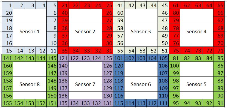
One line in the two-dimensional array like {12, !SENSORACTIVE, 0, 19} says that the first panel is controlled by the sensor on pin 12, has an initial status of not-activated and the LEDs associated with it are LEDs 0 to 19.

I've opted to have fields for the first LED and the last LED of a panel; the latter is not strictly necessary as your panels always have 20 LEDs and the last LED of a panel could actually be calculated.

To make it easier to work with arrays, I have defined a macro #define NUMELEMENTS(x) (sizeof(x) / sizeof(x[0])) that calculates the number of elements in any type of array. The below part of setup() demonstrates how it can be used.

  Serial.begin(115200);
  Serial.print(F("Number of panel rows = "));
  Serial.println(NUMELEMENTS(panels));
  Serial.print(F("Number of panels in row = "));
  Serial.println(NUMELEMENTS(panels[0]));

In setup() you can now iterate over the elements of the array to set the sensor pins to INPUT; change to INPUT_PULLUP if needed.

  for (uint8_t yCnt = 0; yCnt < NUMELEMENTS(panels); yCnt++)
  {
    for (uint8_t xCnt = 0; xCnt < NUMELEMENTS(panels[yCnt]); xCnt++)
    {
      Serial.print(F("Setting sensor pin "));
      Serial.print(panels[yCnt][xCnt].sensorPin);
      Serial.println(F(" to input"));
      pinMode(panels[yCnt][xCnt].sensorPin, INPUT);
    }
  }

In loop() I have declared two variables to count the rows (yCnt) and columns (xCnt). panels[yCnt][xCnt] with e.g. yCnt being 1 and xCnt being 3 refers to the last panel in the last row.

void loop()
{
  static uint8_t xCnt, yCnt;

  Serial.print(F("Processing panels["));
  Serial.print(yCnt);
  Serial.print(F("]["));
  Serial.print(xCnt);
  Serial.println(F("]"));
  
  ...
  ...

Static variables are like global variables but they are only known inside the function that they are declared in. So their vaues will be remembered between successive calls to loop().

Next we read the sensor associated with the selected panel, compare it with the previous state (stored in the panel array) and take action if needed.

  // read sensor
  uint8_t sensorStatus = digitalRead(panels[yCnt][xCnt].sensorPin);

  // state change
  if (sensorStatus != panels[yCnt][xCnt].sensorStatus)
  {
    // remember state of sensor
    panels[yCnt][xCnt].sensorStatus = sensorStatus;

    if (panels[yCnt][xCnt].sensorStatus == SENSORACTIVE)
    {
      ...
      ...
    }
    else
    {
      // panel off
      ...
      ...
    }
    // update physical strip
    strip.show();
  }

And in the last step we increment the column index (xCnt) and if necessary the row index (yCnt).

  // next panel in row
  xCnt++;
  if (xCnt == NUMELEMENTS(panels[yCnt]))
  {
    xCnt = 0;
    // next row
    yCnt++;
  }
  if (yCnt == NUMELEMENTS(panels))
  {
    yCnt = 0;
  }

Each time loop() is called, the sensor of the next panel will be checked (and action will be taken if needed).

The delay(1000) is only there to slow down the process so the first serial prints in loop() don't spam the serial monitor; that delay should not be there when you start expanding the sketch as it results in blocking code.

You can expand the struct definition with other fields if needed (e.g. the colour that should be set); you will also need adjust the PANEL array in that case.

The sketch is prepared to be non-blocking. If you need a responsive interaction, do not use for-loops / while-loops with delay() in them and do not use delay() in general; use millis() for any timing related work. Also don't use show() every time as it takes time; only use it when needed. Your problem will be that during a delay() or show() you can not read any sensors for other panels.

1 Like

But he is not, as far as we can gather, using addressable strips, but a conventional LED scanning matrix.