I have a shaft that will be turned manually. It will not rotate more than 360 degrees or more than one revolution. I need to match the angle or orientation of the manually turned shaft with a shaft that is driven by a servo/stepper motor. It will need to follow the other shaft when a button is pushed. When that button isn't pushed it will run off of a foot pedal that will drive it either clockwise or counterclockwise.
I've been considering an encoder but it will need to be broken so that it can be assembled around the manually turned shaft. Any input is appreciated.
Shaft encoders are available in many sizes and configurations, intended to be mounted on either mechanically or manually turned shafts.
Same principal applies to that of feedback on a basic servo.
In this instance, as well as feedback to the main drive to locate position, use a position feedback from the main drive to the slave drive.
Your query is a bit confusing when you first say the drive is manual then say, oh, no, it's driven from a push button.
Suggest you sort this out first up.
1 Like
The shaft that I need to follow is manually driven. I need this following option to be controlled by a switch (off/on). The servo/stepper will follow the manual one when the follow switch is set to on. When it's off I will control the servo/stepper with a simple control that has clockwise and counterclockwise switches.
I'm trying to explain this without making it more confusing. I might make it worse but here goes. The manual one will never be driven by what I'm trying to build. It's an existing product I will retrofit to. I just need it's direction copied to another shaft that's controlled by a servo. If I turn the manual one left I need the servo driven shaft to follow it to the left etc. When I want control over the servo driven shaft I want this follow mode to turn off.
I will need an encoder if that's my only option that splits in half so it can be assembled around the other shaft. The manual shaft has assemblies on both ends that would prevent me from sliding anything onto the end of it.
Depending on the space available perhaps you could use gears to transmit the motion to the encoder. It would be much simpler to make one of the gears in two parts than to cut an encoder in two. ![]()
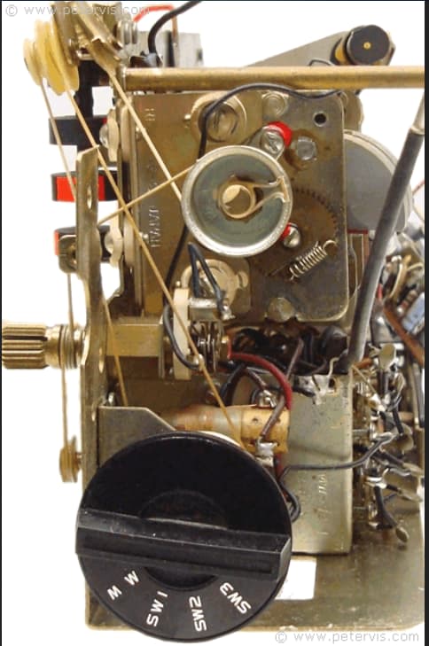
Wrap a strong, waxed thread several times around the driven shaft, and use it as a belt to drive an encoder or indicator. As done in old-time radio tuners.
Fancy example (tuning knob shaft at left edge):
That's a great idea. I could fix a gear around the manual shaft that turns a small gear driven shaft that the encoder mounts to. Making this fit inside of 4" diameter area would be great.
Now I wonder where the saying " a picture/sketch is worth a thousand words"originated...commonly know as a block diagram or circuit diagram.
Perhaps try that.
Would a HMC5883L Compass Sensor work? How accurate are they? I'm not sure what precision I need without building a prototype and testing it. The attached screenshot is a top view. The head on the left is a product that is already manufactured and I would be retrofitting whatever I need to get it's directions. It does have 1.5" diameter shaft below the head. It is shown with the hidden line circle towards the back.

Probably not. The sensor is designed to measure the very weak magnetic field of the Earth, which is strongly distorted or completely overwhelmed by nearby iron or magnetic objects.
Hi,
An out there though.
Put a magnet on the faceplate and get your magnetic angle from the strong fixed field.
Nowhere does it say you have to use the Earth's magnetic field as a reference.
Tom.. ![]()
![]()
![]()
![]()
There do exist non-contact magnetic shaft encoders. Examples:
1 Like
This topic was automatically closed 180 days after the last reply. New replies are no longer allowed.