I have about 5 hours of experience with Arduino at this point so please bare with me.
I want to make a simple voltage meter using an Pro Mini 328 with a 1.8" TFT LCD display. I only need to check a max of 4.2v, one cell lipo.
I want to check each cell of a 2 or 3 cell lipo....3 cell is unlikely as I only use 2 cell lipo's to power the receiver's and ignition's in my RC planes.
I want to push a momentary switch and have the cell voltages displayed, as well it will tell me which battery it's reading.
So forget all the questions I'll have down the line about this I only want to know one thing right now.
Every volt meter I see is using a voltage divider. What is the max voltage that can be input on the sensing pins? If it's 5v max then I will not need a voltage divider...I cannot find this info anywhere.
The analog input pins can read a voltage range of 0 to whatever Vcc is powering the AVR chip. Note the Pro mini boards can be had in 3.3vdc and 5.0vdc versions, so assuming you have the 5 volt version you would not require a voltage divider. Applying any negative voltage and any voltage above the chip's Vcc to a analog input (or digital for that matter) pin will result in pin damage.
Mine are 5V so a single cell voltage will work fine and keep it simple.
I bought two pro mini's, one to mess with and one to put in a plane. I loaded the program with no problem but I'm not sure what happened, when I wired up a 16x2 LCD I can no longer load a sketch on to it. Now I get avrdude: stk500_getsync(): not in sync: resp=0x00. Can't clear the eeprom so I assume I need to reload a boot loader.
I thought it was going to be a straight forward project....not.
I did not want to brick the other one so that is why I really wanted to be sure about the voltage.
Thanks for the information. At least now I can apply voltage and start getting a working program.
Do you use external power supply ? and you try do the upgrade of the firmware ? if not ty or try to cut the power in the lcd display and try to upload.
Also try to see on arduino ide it is still available the serial port number you had at the first upload ?
I can program the other pro mini without any problems. The LCD was pulled from an old lipo charger and it was working when I pulled it so I don't think that was the cause. I checked and rechecked the wiring before I did anything and it was wired correctly.
One thing I didn't do was put a 10k pot for the contrast as I was more concerned with just having it say "hello world" and then at least I would know I had something to work with.
Once I saw that I had nothing on the LCD I disconnected it and was just going to start from scratch and clear the eeprom and that's when I got avrdude: stk500_getsync(): not in sync: resp=0x00.
I did the test that echo's what I type in on the serial monitor and that works fine so I don't the it's bricked.
I have a ISP programmer and I tried using that but for what ever reason that does not show up in the Arduino IDE.
I have to say I was very bummed that 10 minutes into this project I had a major problem, it's a good thing I bought two...I mean they were only 4 bucks each so I will get more but it sucks because it should be usable again if I can get it to respond.
I do have an external power supply that I am using for testing the voltage input however there was no voltage input applied during the initial LCD test.
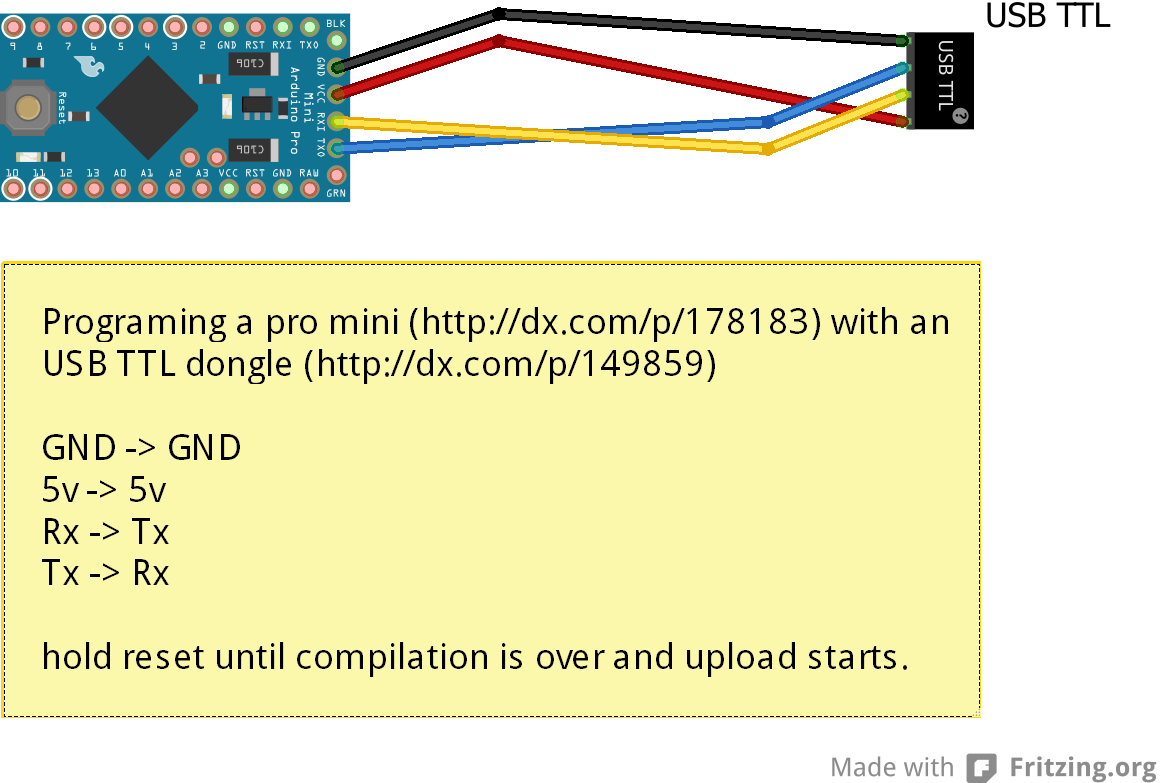
I'm using a FT232RL USB to Serial adapter module USB TO 232 For Arduino to interface with the pro mini which from what I read had a reset line.
The TFT LCD should be here today and I'm hoping that works as I will NOT hook up the 16x2 LCD to the good chip and end having nothing to work with.
If I can the get first PM to work again then I have a back up to try the LCD again. I've read where it's possible to hold the reset button and release it at just the right time and sometimes that works, well it hasn't yet after about 50 tries. I could try and burn the bootloader hex file directly from avrdude but I really don't want to spend a ton of time messing with that yet.
The message you got i have sometimes with the Leonardo board and the tip to avoid it is to press the reset button on board when the arduino ide finish the compile and try to start the upload.
How can I load the FW onto it....for that matter where can I find it?
EDIT: Things are getting very strange now. I plugged it in and I was able to clear the eeprom. I then was able to load a simple voltage sketch that prints out to the serial monitor and it was working, then it stopped...W T F.