that's the thing, it's not dominant, because if it was then i should see +3 or -3 on the signal pair, instead i see 0v when they are both attached but with opposite signals, if for example DI high was dominant i would have no problems to pull DI low on all inactive slaves, same thing for the reverse, if DI low was dominant i would pull high all the inactive ones, but instead they are all trying to pull the line to the state indicated by the DI, so i have 3 inactive devices pulling the line one way, and one active device trying to pull the line to the active transmission without succeeding because 3v1
garbage...
the RO line is pulling the RX, TX and DI to high level (3v3) when idle, so TX is unable send any data outside... at this point i could put the resistor on the RO pin instead of the TX because right now it isn't working... BRB
---edit---
well, moving the resistor to the RO line just reversed the problem, it can send data out from the slave but cannot receive because TX is holding the line high when idle, i'll try tinkering with the software to disable tx pin when idle... RO line will keep it high
Bear in mind that the active state, the dominant state, is a '0' (3v!).
i believe the outputs are totem poles and not NPN/PNP transistor and pull-up/down, because if 2 devices with DI in 2 different states were to be wired together, one should drive the signal pair correctly and the other would be dormant... which is not the case here, they cancel each other out and i get 0v differential instead of +/-3...
fuck it, i'll get me some ADM3485 for 2.50 euros each
mouser link
half duplex is more than enough in my case, less wires, same board, couple different traces
also tried pulling TX low on idle and RO pulling it high but for some reason i don't even get the echo back, the TX from the slave works but not the RX
it's late so see you tomorrow ![]()
That's what I said in post #28
update...
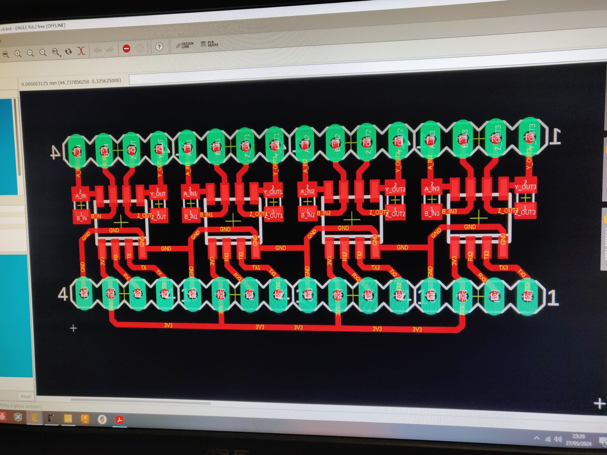
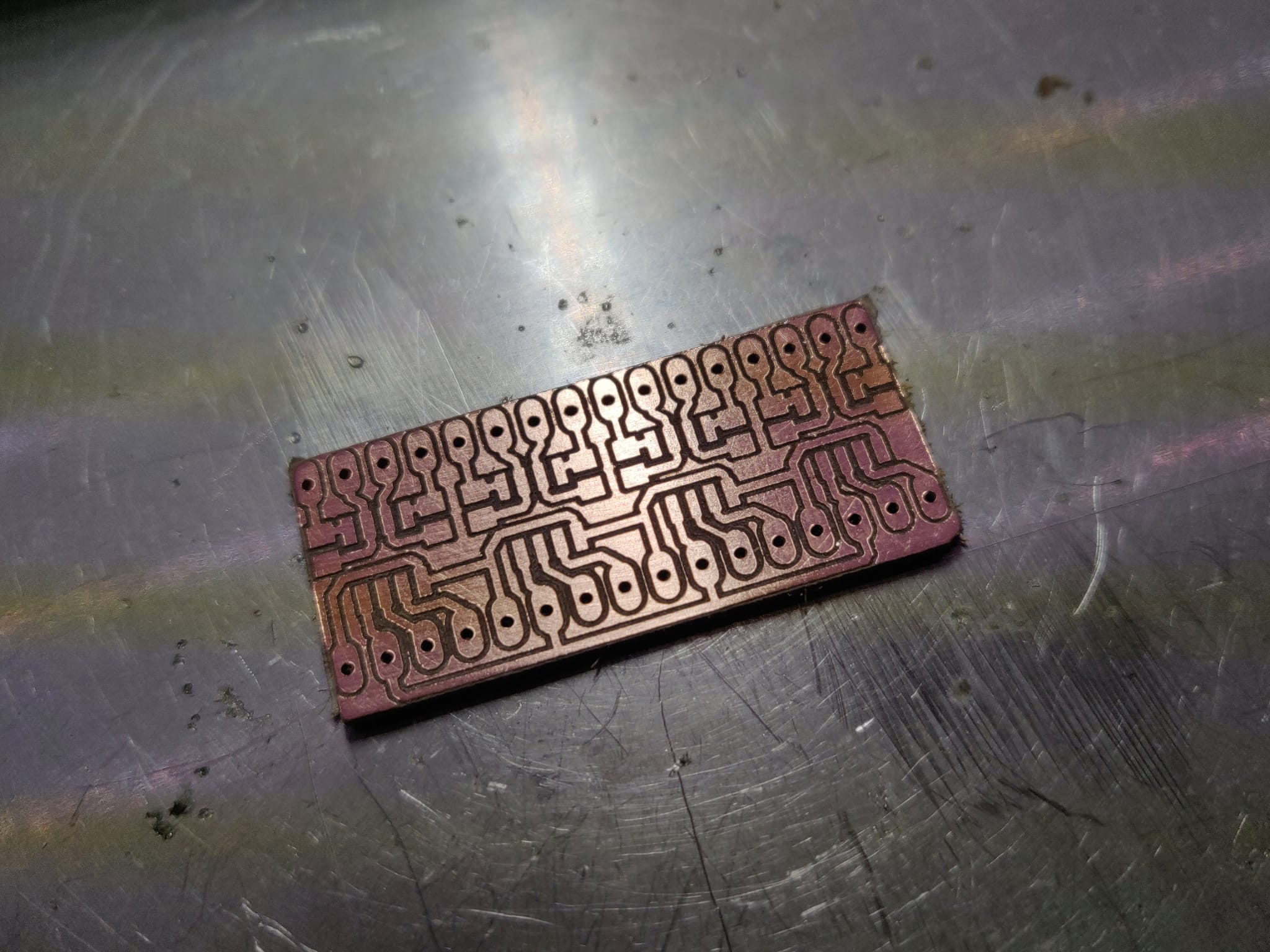
i'll divide the network in 4 single ended lines to avoid buying different chips when i have a hundred of these lying around.
on the master simply wire 4 parallel MAX3490 with 3V3, GND and TX in common, while RX is to be wired to 4 different inputs, and just switch the RX pin to whatever node i'm waiting to respond... (because i think that even the RO is totem pole and shorting it with other chips will create conflicts)
how? i'm using PIC24EP256MC204 on the master... it has remappable pins, just chose 4 different pins and remap the RX to the pin wired to the RO of the line i want... so i dont actually have to remake any board from scratch... just a small RS485 splitter board with pin headers, 4 MAX3490 and 4 resistors
PRO:
-i'll make it today in 2 hours max
-hey... it's free
-no waste boards
CONS:
-more cables since each slave has it's own personal cable, but then again... i have recycled ethernet cables laying around (taken out after a restoration)
-less expandable since splitter has 4 chips and that's it, plus i would need to put even more cables, and i dont think there is any more space in the tubes

Not elegant but a true engineering solution.
This topic was automatically closed 180 days after the last reply. New replies are no longer allowed.