My project requires 9 alphanumeric (16-segment, no decimal point) displays, and I'm trying to keep the component count low so it will all fit easily in the enclosure. To that end, I would like to use the MAX7219 to drive the displays... each "digit" on the 7219 would drive half of the 16-segment display, giving me a max of 4 digits per chip, and only 3 chips total. My displays are common anode, and I'll be transposing the bit matrix in the library to accommodate the "backwards" wiring, so unfortunately the MAX6954 is not an option since the matrix won't transpose properly. (See my post here: MAX7219 and Common Anode displays with LedControl - LEDs and Multiplexing - Arduino Forum)
I got as far as hooking up the display (AND'ing two digit outputs to the common pin on the display and doubling up the segment pins to drive two segments each) before I realized that the way I had hooked it up, each half would light up simultaneously. (Incidentally, this is as far as yesyes got in his archived thread here: http://arduino.cc/forum/index.php/topic,22652.0.html) Obviously I need a way to keep each half separate.
The solution I thought up was to put an NPN transistor at each display pin, and activate the base with a signal from the digit pin. That way, when digit 1a is on, the transistors will allow current to flow to just the segment pins going to the first half of the digit and not the other half, and the other way around when digit 1b is on. (See super-simplified diagram below.) But this adds up to a ridiculous number of transistors... 16 per digit! That's a lot of components. Is there a better way to handle this?
74LS154 1 of 16 selector, 9 PNP transistors (source for common anode of selected display), 2 TPIC6B595 (sink for cathodes of all displays - send 9 segment As to bit 0 on chain of shift registers, 9 segment Bs to bit 0 ... 9 segment Ps to bit 15). The selector holds all but one transistor high and therefore off and one low and therefore selected. Prior to that, you shift in the segments you want on that display.
i.e.
Shift in segments you want on display #1
Turn on display #1
Wait 1ms
Turn off display #1
Shift in segments you want on display #2
Turn on display #2
Wait 1ms
Turn off display #2
...
Probably too complex, but it would give you total control of all the segments at a 1/9 duty cycle. Of course, it becomes your duty to continually refresh them (at about 900Hz), maybe you don't want to do that.
Yeah, that's a good suggestion, and it's something I'd considered (not that specific chip, maybe, but a 20-port I/O expander). But it makes the Arduino do all the work of syncing the displays and updating everything. I'm running 39 separate displays (15 dual 7-segment, 9 single 16-segment), plus a couple standalone LEDs, from the same Arduino... I need to offload the multiplexing as much as possible.
Why not get some common cathode displays and make your life easier all around, both hardware wiring and software control, just revert back to writing registers in the MAX7219.
The displays I'm using are both very difficult to find and rather expensive, so I'd prefer not to just toss the hardware I have now.
Most of the other options for switching the outputs I've found would either require some reflow soldering (which I can't do) or wiring up dual quad-SPDT analog switches for each display (which would not do much for my component count).
I do have some MAX6969 chips (Mixed-signal and digital signal processing ICs | Analog Devices) which would do exactly what I need to do and only require 9 chips for the whole display array. I think at this point they're the better option than trying to jury-rig three 7219 chips.
Just started working on a similar problem. (8) 2 digit 16-segment common cathode displays driven by MAX7219 drivers downstream of (2) MAX7221 drivers. How about draining two segments A->H on one digit and K->U on another digit. And driving each common anode with two digit pins through dual input OR gates into switching FETs if necessary. With either common anode or common cathode displays you will still have to bit map the display. What microcontroller are you using?
A dedicated atmega1280 40 pin dip to drive your displays. Enough pins for 16 cathodes and 9 anodes (with 9 pnp transistors attached). It could communicate to your other Ardino via i2c or serial.
Current limits of the chip might be the problem. It has 2 ground pins and 2 Vcc pins, although one is supposed to be for Analog, so not sure whether that means a total max current of 200mA or perhaps 400mA?
If it is 400mA, that should be enough to sink 20mA from each of 16 cathodes, as long as you can spread the current over the various groups of pins which have 150mA or 100mA limits. Combined with a 1:9 multiplex ratio, it might be bright enough.
Need someone familliar with the 1280's data sheet to confirm this. Bob?
Failing that you would be looking at another 16 npns...
Sadly, the "take home message" here is that you simply cannot use a MAX7219 to drive a display which has a single common - anode or cathode - to 16 segments.
Interesting to read this because I want to control 1080 LED's/digits with the smallest amount of chips possible...
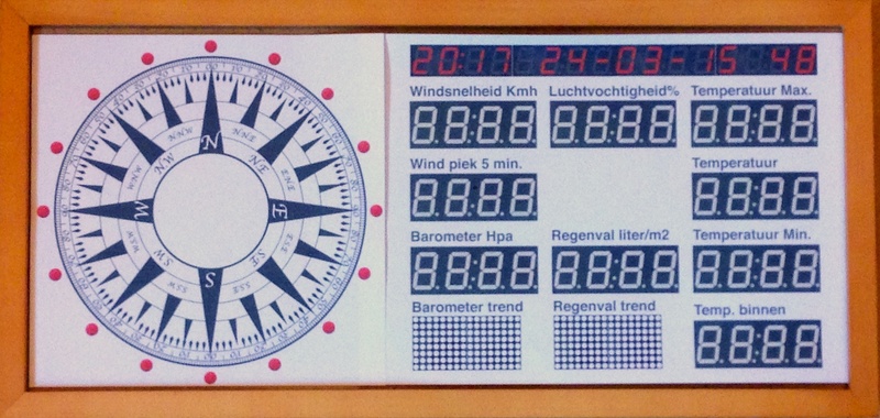
I like the Maxim 7219 chips very much but my Weather View display is build up using Alphanumeric displays instead of 7 segment. (the 0,8 inch height displays are relatively cheap here)
So I think the shift register approach is the best after reading all the comments here?
Any thoughts on that?
Sadly, the "take home message" here is that you simply cannot use a MAX7219 to drive a display which has a single common - anode or cathode - to 16 segments.
Not true. Check out my post on how to drive 14/16 segment common cathode displays with 2 x MAX7221/MAX7219:
Well, as the ol' Mike here will say to you, if you want to run the chip in direct contradiction to the manufacturer’s specifications, that's your problem.
Selling a product which does this, or advising other people to do it - that's not such a good idea!
So why do you think MAX7219 is not covered by that app note?
Maxim uses one datasheet for both MAX7221 and MAX7219. In that datasheet, they also specify (page 6):
MAX7219/MAX7221 Differences
The MAX7219 and MAX7221 are identical except for two parameters: the MAX7221 segment drivers are
slew-rate limited to reduce electromagnetic interference (EMI), and its serial interface is fully SPI compatible
florinc:
So why do you think MAX7219 is not covered by that app note?
Maxim uses one datasheet for both MAX7221 and MAX7219. In that datasheet, they also specify (page 6):
Seven Segment Drives and Decimal Point Drive that source current to the display. On the MAX7219, when a segment driver is turned off it is pulled to GND. The MAX7221 segment drivers are high-impedance when turned off.
Bold added.
Semantics. When they say:
The MAX7219 and MAX7221 are identical except for two parameters:
The word "parameters" refers to dynamic behaviours rather than strict hardware functions. Albeit that is a little misleading.
In any case, the reason the MAX7219 is not covered by that app note is that the app note is simply not suitable for the MAX7219. And that is it.
I kind of thought you knew this when in your blog you cited the "Playground" page which points out:
Note that the MAX7221 is definitely preferred over the MAX7219 for this technique. This is because in shutdown, the MAX7221 digit drivers are high impedance, rather than V+ as in the MAX7219.
However, I have used both parts in my projects with no noticeable difference. I don't know why the MAX7219 works - but it does! So if you only have MAX7219's it's worth trying them
Do you have an explanation for why it works though?
Seven Segment Drives and Decimal Point Drive that source current to the display. On the MAX7219, when a segment driver is turned off it is pulled to GND. The MAX7221 segment drivers are high-impedance when turned off
I guess you realize that this is not relevant, since the segments are not common (in the 2xMAX7219 multiplexed setup), just the digit drivers.
What is relevant is this:
The MAX7219 pulls the digit outputs to V+ when turned off. The MAX7221’s digit drivers are high-impedance when turned off.
Now think of the internal npn transitors for sinking the digit lines. The "digit output to V+" is realized through a pullup resistor. When one MAX7219 is shutdown, the digit line of the one that is on will sink a bit more current (LED current + current through the pullup resistor from the one in shutdown mode). If the pullup resistor is 10k (let's say), the extra current is 0.1mA (5V/10k).
If it's not clear, I could draw a schematic.
Please let me know what you think.
Well, I picked one, couldn't be bothered quoting both!
florinc:
Now think of the internal npn transistors for sinking the digit lines. The "digit output to V+" is realised through a pullup resistor. When one MAX7219 is shutdown, the digit line of the one that is on will sink a bit more current (LED current + current through the pullup resistor from the one in shutdown mode). If the pullup resistor is 10k (let's say), the extra current is 0.1mA (5V/10k).
Where do you get this pull-up resistor? I am offhand unable to find it.
The Digit Drive Source Current is quoted as 2 mA minimum at (V+ - 0.3V) (page 2, bottom of chart). If this was a resistor, then when pulled down to nearly ground by the alternate digit, it would source at least 30 mA. Frankly, I doubt it is a resistor, but it clearly will be a substantial current.
By the way, you might ask why the MAX7219 has these totem pole outputs or indeed why it exists? An interesting muse; the answer would be in order to control external buffers which may employ non-switchable current sources on their inputs. In general, you could consider the MAX7221 the more versatile one and thus, preferable.