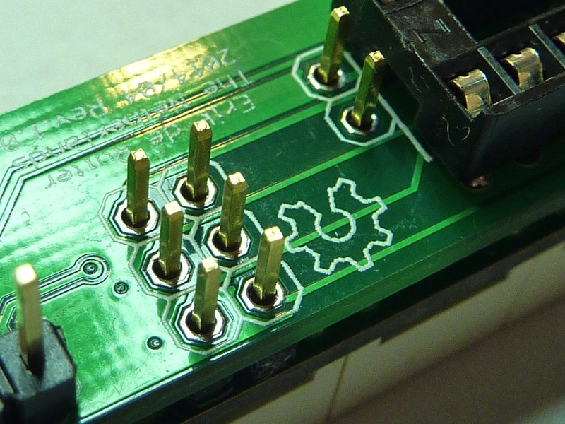
I am not 100% confident that the trace width of my Maxim 7219 PCB is sufficient... I did use a trace width calculator and I think it's OK now but can a more experienced member shed his/her light on my PCB design?
For the Maxim 7219 to DIGIT traces, I use 16 mil, for the SEG traces 12 mil.
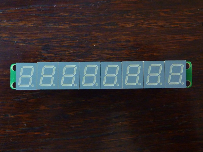
The displays are from Kingbright. SC39-11SRWA
DC Forward Current: 30mA
PEAK Forward Current: 155mA (1/10 Duty Cycle, 0.1ms Pulse Width)
16 mil is plenty.
I don't see any traces from the chip to the display tho. How are those 15 or 16 connections being made?
8 digits
7 or 8 segments (Decimal Point being used?)
Too small on my display, can't see that. Thanks.
I'm very sorry I did not reply sooner!! I thought I got email when replays are given...
Thank you very much for your info, I did order the PCB's and it's working perfectly
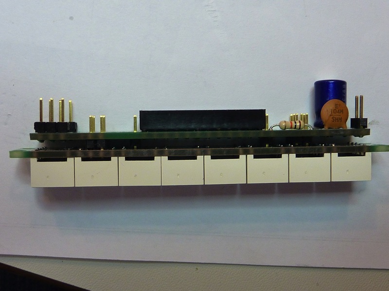
Yes, the PCB's are connected with header connectors to get the smallest footprint possible.


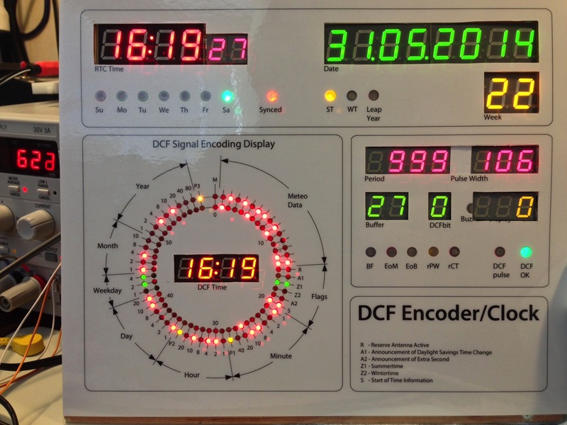
The display is very handy to display various parameters. I can leave displays out when they are not needed.
For the Period/Pulse and Buffer/Bit/Error display , I used this PCB.
(front panel is not ready yet...)
Thanks, it's my first Arduino/electronics project. Had to learn a lot but making countless mistakes did produce something useful (for me a least)