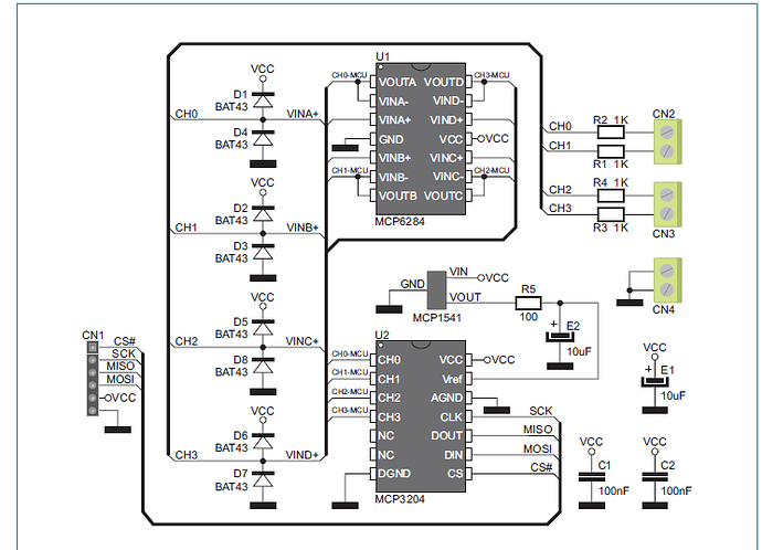
Hi All
This is my first post has I've only just started playing with the Arduino after doing plenty of reading.
I'm trying to make a simple volt mere using the MCP3204, Just getting CH0 to read (I've got to channels working) after a little playing I've got it to read the same as my Fluke meter but the trouble is the reading are a little jumpy bouncing around is there a way to improve it to get stable readings ? The idea is I want to display it on LCD and this will show on the LCD more
This is the sample that is been sent out
RAW1: 1628
VOLTS1: 13.11
RAW1: 1630
VOLTS1: 13.13
RAW1: 1629
VOLTS1: 13.12
RAW1: 1627
VOLTS1: 13.10
RAW1: 1628
VOLTS1: 13.11
RAW1: 1628
VOLTS1: 13.11
RAW1: 1628
VOLTS1: 13.11
RAW1: 1635
VOLTS1: 13.17
RAW1: 1628
VOLTS1: 13.11
RAW1: 1628
VOLTS1: 13.11
Here is the code I have working, I know there may be better ways to improve code but it's my first attempt at it.
#define SELPIN 10 //Selection Pin
#define DATAOUT 11//MOSI
#define DATAIN  12//MISO
#define SPICLOCK  13//Clock
int readvalue;
 int analogInput = 1;
  float vout = 0.0;
  float vin = 0.0;
  float R1 = 33150.0;    // !! resistance of R1 !!
  float R2 = 4699.0;     // !! resistance of R2 !!

void setup(){
 //set pin modes
 pinMode(SELPIN, OUTPUT);
 pinMode(DATAOUT, OUTPUT);
 pinMode(DATAIN, INPUT);
 pinMode(SPICLOCK, OUTPUT);
 //disable device to start with
 digitalWrite(SELPIN,HIGH);
 digitalWrite(DATAOUT,LOW);
 digitalWrite(SPICLOCK,LOW);

 Serial.begin(9600);

}

int read_adc(int channel){
  int adcvalue = 0;
  byte commandbits = B11000000; //command bits - start, mode, chn (3), dont care (3)

  //allow channel selection
  commandbits|=((channel-1)<<3);

  digitalWrite(SELPIN,LOW); //Select adc
  // setup bits to be written
  for (int i=7; i>=3; i--){
    digitalWrite(DATAOUT,commandbits&1<<i);
    //cycle clock
    digitalWrite(SPICLOCK,HIGH);
    digitalWrite(SPICLOCK,LOW);
  }

  digitalWrite(SPICLOCK,HIGH);    //ignores 2 null bits
  digitalWrite(SPICLOCK,LOW);
  digitalWrite(SPICLOCK,HIGH);
  digitalWrite(SPICLOCK,LOW);

  //read bits from adc
  for (int i=11; i>=0; i--){
    adcvalue+=digitalRead(DATAIN)<<i;
    //cycle clock
    digitalWrite(SPICLOCK,HIGH);
    digitalWrite(SPICLOCK,LOW);
  }
  digitalWrite(SELPIN, HIGH); //turn off device
  return adcvalue;
}


void loop() {
 readvalue = read_adc(1);
 vout = (readvalue * 4.095) / 4095.0;
 vin = vout / (R2/(R1+R2));
 Serial.print("RAW1: ");
Serial.println(readvalue);
 Serial.print("VOLTS1: ");
Serial.println(vin);
 //readvalue = read_adc(2);
 //vout = (readvalue * 5.0) / 4095.0;
// vin = vout / (R2/(R1+R2));
// Serial.print("RAW2: ");
// Serial.println(readvalue);
// Serial.print("VOLTS2: ");
// Serial.println(vin);
// Serial.print("  ");

 delay(1000);
}
I will try later to add a little menu system to enable to calibrate the values of R1&R2 or one or the other
