HACF:
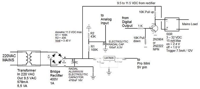
First, where I am, the voltage number they give for the mains voltage is an RMS value. If they do the same thing where you are, you're going to see greater than 12 Volts out of your transformer. Point is... If they do the same thing where you are, you haven't have sized your voltage divider resistors properly.
OK. So the correct route would be to first measure the voltage from the AC-AC transformer and bridge rectifier ( before the LM7805 ), and then size the voltage divider resistors to suit that reading. My ( uneducated ) guess is that it may be better to size the resistors so that the analog voltage maximum is a lot lower than the 5V limit of the input pin - say somewhere around 2.5V ?
HACF:
Second, I think your analog input voltage is going to be noisy due to ripple. I don't think 0.33 uF is enough capacitance to smooth the waveform coming off your bridge. You will probably get different voltage readings depending on where in the cycle you take your measurement.
Understood. That 0.33 uF capacitor was taken from the spec sheet of the voltage regulator. I have since read some other articles that explain that the output of the bridge rectifier should be passed through a capacitor to "level out" and smooth the ripple in the DC current.
I have no idea how to determine what type of capacitor to use, nor what rating / specs it should have. Advice in this really appreciated.
HACF:
Third, you are trying to measure the voltage level of an unregulated source, while at the same time you're drawing a changing amount of energy from that source. You have a variable load (SSR on vs. SSR off) on an unregulated supply and because of that, you are going to get more ripple when you turn on the SSR. If you're planning to draw 7.5 mA off your unregulated supply I can guarantee that your 0.33 uF cap isn't enough and the voltage you're trying to measure is going to be all over the place. Your microcontroller is going to be a variable load as well although compared to your SSR switching off or on, you might be able to ignore the microcontroller.
OK. But if the SSR can be activated with an input range of 3-32VDC, could I not then rather use the 5V output of the LM7805 to activate the SSR ( instead of the 12V from the rectifier ). Would this still affect the voltage between the rectifier and the LM7805 ?
HACF:
Fourth, Are you sure you're going to have enough resolution on your A/D output to resolve what it is you're trying to do? Account for the RMS voltage and size your divider accordingly and then calculate the theoretical number of bits change you'll have per volt change out at the 220 line? How much do you need and do you have enough?
What I am aiming for here is to determine if the mains voltage is in the ranges :
- below 170VAC
- 170 to 200VAC
- 200 to 230VAC
- above 230VAC
Depending on the type of equipment being controlled by the SSR, I would use the mains voltage to determine if the mains is at a level that is sufficient to meet the requirements of the equipment. Some equipment has a power supply that can accept, lets say, 110 to 220VAC, while others may require an input of 220VAC.
HACF:
Hope that helps?
Yes, you have been a fantastic help. Thank You. Really appreciate the points you made.