Sorry, still makes no sense to me. What is the thing that you label "Variable Resistive Load" in your diagrams?
Is it just a piece of wire? If so how long is it and what gauge is it?
Is it a fixed resistor?
Is it an incandescent light filament?
Is it a piece of semiconductor?
Is it a varistor?
Hi @Grumpy_Mike ,
to be clear, I can not disclose the picture of the resistor nor mention its material. Apologies if it sounds arrogant but its not my purpose.
It is a pure metallic resistor wire with 50 um diameter and >5 cm length. The resistance can change by 10% as a function of the input power.
It may work if you put a sense resistor in the positive of the driver chip.
You could use a Op Amp Breakout board. However it will increase the voltage from the sense resistor(s) but you still have to use the Arduino A/D to capture the value.
I understand your concern about the details of your test resistor, but I don't really need to know. However can you post a Scope screenshot of the voltage at the sense resistor(s). Seeing the waveform will help suggest a method of measurement and won't divulge any info on the dynamics of your load.
The op amp would be configured something like this:
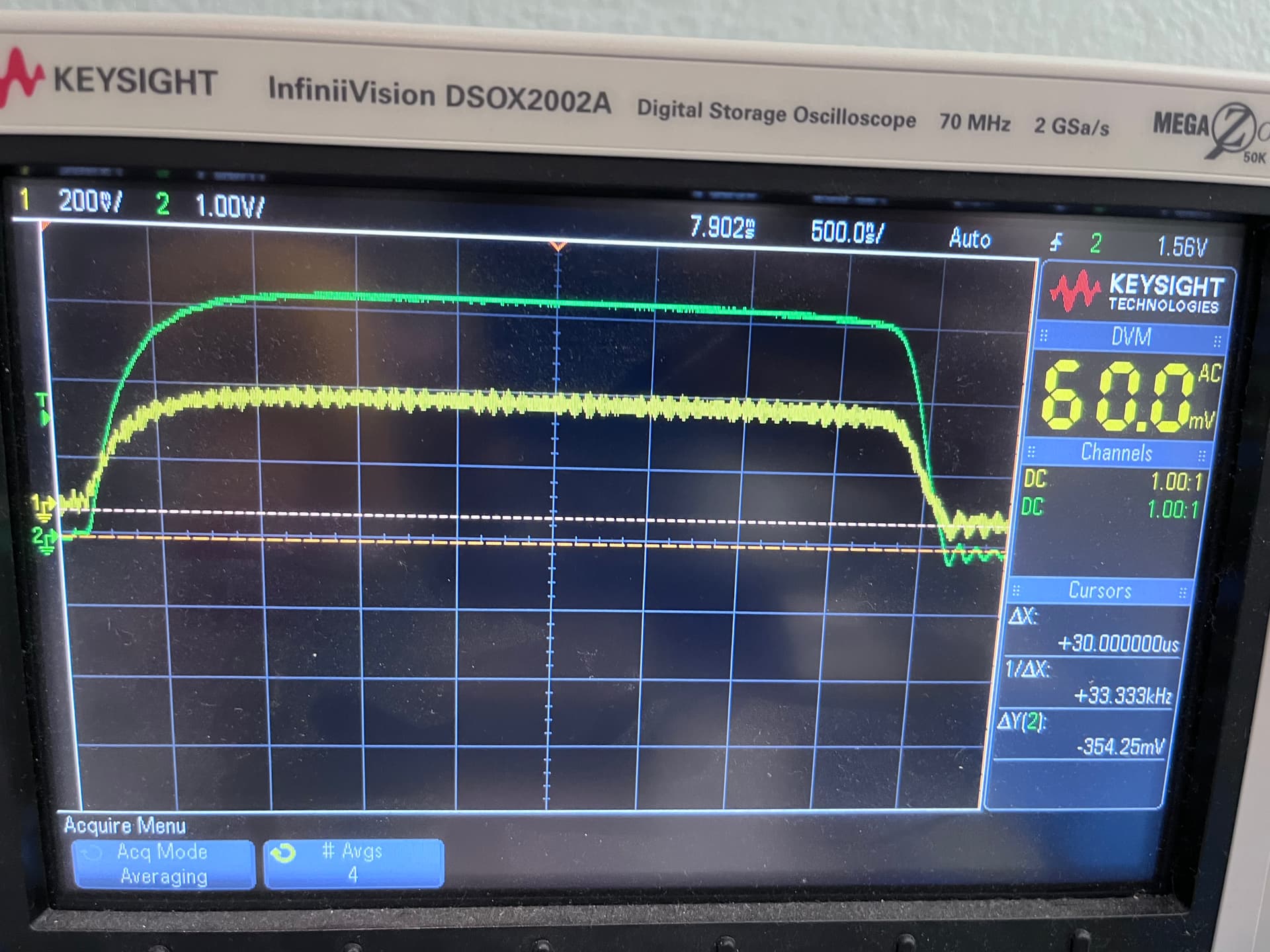
Thanks a lot everyone for the great help. I will try out the suggestion in coming days. Here is the screenshot of the input voltage I have in latest set up (Yellow with scale of 1V per division) and green the current through the current sense resistor (200mv per division).
OK
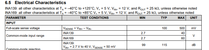
So you need to be able to sense about 200mv, more importantly you will need to filter out some of the noise.
I can lead you through the steps if you want. Many of the steps are simple but require measuring at specific physical locations.
Let me know how you wish to proceed.
It would be interesting to see the signal with the timescale changed from 20µ-seconds to 1 µ-second and 500 nano-second so that one of the small pulses is shown filling 2/3 of the screen or the whole screen.
To see the rising edge you may have to change the horizontal position.
It is a 70 MHz 2Gs digital storage-oscilloscope. So after recording at 1 µ-second in singleshot-mode you could show the recorded signal at a time resolution of 200 nano-seconds, 50ns ,20ns etc.
Hi @StefanL38 I took below pictures of one pulse with out an averaging and with averaging on Oscilloscope. Please let me know if I can take better pictures
I also tried this configuration and it did not work
@johnerrington what are good values for C and R for PWM frequency of 10KHz? I tried the circuit but as @JohnRob mentioned I am afraid its just too small of voltage
We have been floundering around because you initially gave so little information
"I am trying to measure the amplitude of a PWM signal using Ardunio. I know the duty cycle and the frequency of the signal. "
So we know:
the range of voltages? NO
the frequency? the duty cycle?
how it is grounded?
the source impedance?
where the noise is coming from?
the precision to which you want to measure the "amplitude"
trawling through the thread (finally at #47, #50) it looks as if the signal is ground referenced with a peak amplitude of 400mV, rep rate of 10kHz and pulse width (presumably variable) shown as about 5usec.
So: you need to make the voltage bigger to be able to measure it.
A 5usec pulse has frequency components at and above 200kHz so you will need an amplifier that can work at those frequencies.
The SparkFun OpAmp Breakout - LMV358 - BOB-09816 - SparkFun Electronics
uses a lmv358 which has a gbw of 1Mhz
"The bandwidth is set to 15.9kHz by a pair of feedback capacitors, or over 100kHz with the caps removed." so its too slow.
An op amp such as the AD823 could be used as a 2 stage amplifier to give a suitable voltage for measurement - you would still need a detector, peak hold or lock-in amplifier to measure the peak voltage. And you would need to get rid of the noise - although the bandwidth limityataion of the amplifier might well do that.
Thanks a lot @johnerrington for the explanation and my apologies to all the experts here for not properly describing my problem initially. I increased the rep rate of the Ardunio PWM generator from the standard 1KHz to 10KHz only to help with the initial Low Pass filter circuit I made to measure the DC component. My input signal is not complex and I can even use a rep rate of 500Hz PWM frequency if needed. This will increase my pulse width to 100us (with frequency component of 10KHz). Do you think this will help my measurement?
It will make your task a lot easier.
You can measure the average voltage in a pwm waveform with a low pass filter. It WONT tell you the peak voltage (ie amplitude)
Well it IS because it has high harmonics, and to measure it properly you need to preserve those harmonics, else you will degrade the shape of your pulse.
If you dont expect a phase shift between the driving signal and the measurement signal you can use a simple sample & hold circuit as a "lock in amplifier",
which unlike the peak hold will give you a precise and instantaneous response.
You will still need to amplify your signal. As it has a predictable amplitude around 400mV as shown on the 'scope you would need a gain of around 8 to match the FSR of the Due ADC.
You will need to account for the lag between changing the duty cycle and the resistance changing, because I suspect the effect you are measuring is affected by the temperature of the wire, which changes with the amount of current through the wire. Also may need to account for external conditions, such as ambient temperature and air movement.
As the TO wants to keep the real application a secret
he is willing to develop a 100.000 cps scissoring machine for beeing able to mow a football-arena within two hours by using a super-high-speed-electric scissoring-machine.
This is like
here is an analogon that shall show what can happen if just ask for details:
Newbee: "I want to do better cutting please help me sharpening. "
Expert: Sure I can help you. What kind of cutting-tool are you using?
Newbee: a scissor.
Expert: OK take this sharpening tool
Newbee: Yea works great Next question How can I make it cut faster I need to finish faster.
expert: Motorised scissors.
newbee Yea works great though still not fast enough.
expert: Ok can you give an overview about what you are cutting.
newbee: the green of a football-arena.
expert: Oha! take a big mowing tractor with a seven boom spindel-mower and GPS-steering
In the beginning the newbee always just told details.
The expert was assuming the newbee knows that his basic approach is well suited.
which turns out to be very bad suited
that's the reason why it is always a good idea to give an overview and to explain what shall happen in the end.
But in hobbying everything is allowed as long as it is not against the law.
So you are free to decide to dance in circles without moving forward.
Just another way of collecting experience.
Hi everyone and happy new year. I found a paper that achieved what I want to do with a DC power source and a Darlington Driver. Below is the schematic of their set up to measure the resistance of filly resistive DUT load. The goal is to measure the Va as a function of the duty cycle of the PWM generator. At each falling edge of the input PWM signal, a Vamp value is recorded as VA. In other words, one VA is recorded during each PWM cycle. The input PWM has a 100 Hz frequency. Hopefully this graph better describe my problem. I am wondering 1- Can I do the same thing with Ardunio + a motor shield V3 without the need for Darlington Driver and DC power source and 2- If yes, how?
More desciption of the set up:
Acquisition card: A multifunction data acquisition card (±5 V full-scale range, 12-bit resolution; PCI-1711, Advantech) to measure the amplified signal (Vamp) and to send the PWM signal via the digital output
Driver: A Darlington driver IC (ULN2003AP) as a switching element
A DC voltage source Vs = 6 volts
A resistor, R, was connected to prevent burning DUT
VCE of the Darlington driver was then amplified by a differential amplifier. The amplified voltage Vamp was measured by the data acquisition card.
I am not familiar with the Darlington Driver but this is exactly what I want to do. They did it for measuring the change in the resistance of their fully resistive load (in their case, shape memory alloy). Here is the image of their set up
I am not sure what is VCE of the driver but this is the one they used to measure. I think the idea is that the voltage drop across the Darlington slightly changes by change in the resistance of the DUT. They amplify this change in VCE to measure the change in the resistance. But for doing this, they need to have internal resistance of the darlington. my goal is to not have the Darlington and do the same thing by measruing the voltage across the "R" in this circuit.
I have a motor shield that basically is a class D amplifier and switches between 0-5 volts or 0-9 volts (depends on the input of the power supply)