Where is the photodiode?
yeah, BPW21R is connected to the pin 2 of the amplifier. Also the reason for connecting the cathode was to read the output of the analog pin to see the varying voltages when the LED turns on/off. The capacitor at the output is a low-pass filter im desiging to remove the noise.
That's the same as the other schematic
Where is the photodiode?
as said:
- don't connect the catode to the analog pin
- the 'low pass' you are using is not a low pass: connect the resitor from the output of the opamp to the input of the a/d, connect the capacitor from the input of the a/d to gnd
ADDITION
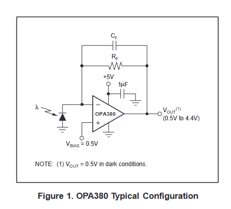
also no experience with this amplifier but it seem that it can't work at 0V so you shold use something like this ( ie connecting in+ to a bias voltage 0.5V for example ):
1 Like

1 Like
@gemera
So how is any of this related to the code and wiring diagram you show in post #1?
Are you still trying to make that circuit work with an LM741?
1 Like

oh yeah, the earlier circuit was to test the working of the photodiode
Oh okay, thanks for this. If it is wrong to connect cathode to the analog pin, can I connect the cathode instead just to see the different values measured by the photodiode

this is the photodiode in the diagram, i dont know it answers your question
Here is how TI recommends to connect the OP380. Datasheet

1 Like

If you connect the catode to in-, on the cathode or on in-, you will see exactly the same potential as in in+ ( ie 0V or the vbias, depending on where you connect in+ )
Just to clarify please, are you referring to the cathode of the photodiode please
The type of circuit you use will depend on what you are trying to do.
Are you trying to measur light intensity like a light meter, measure optical pulses or send data optically?
im building a temperature sensor using optical fiber. i currently need an amplified signal to work before i put in my optical fiber
I think you are off on the wrong foot.
Optical fibers use 850nm or 1300nm wavelength light.
Your photodiode is specifically designed to mimic the human eye, which can't see either of those wavelengths.
Also you will be sending the data digitally and your circuit may not be fast enough.
I think it's time you tell us what you are actually trying to do.
The coating material for the fiber reacts to light at wavelength 450nm - 550nm. which is why a blue LED is being used.
Without adding the fiber, the basic idea is to amplfiier the signal from the LED using the amplfier and ADC.
Is the signal varying in intensity and if so at what frequency or is it some kind of pulsed signal of constant amplitude.
1 Like
yes ( I was only saying that there is no measurable 'signal' on the diode cathode )
1 Like