Hi,
I want to use a BPW20RF photodiode and an operational amplifier. I am very new to all this and got confused how to set up the amplifier. When I directly plug in the photodiode in A0 and use a reference resistor of 30 Ohm, I get values of 0 to ~80 if I point directly with a flashlight on the sensor. Using an op-amp I want to increase this voltage to cover the whole level of 0 to 1023. Im using a 3.3V Mini, therefor my maximum V_i (light pointing on sensor) was around 0.28 V. This I want to amplify around 11fold. Using a formula I found for the gain of op-amps (V_0 = V_i * (1 + (R2/R1))) when R2 is 10x the value as R1, e.g. 10K and 1K.
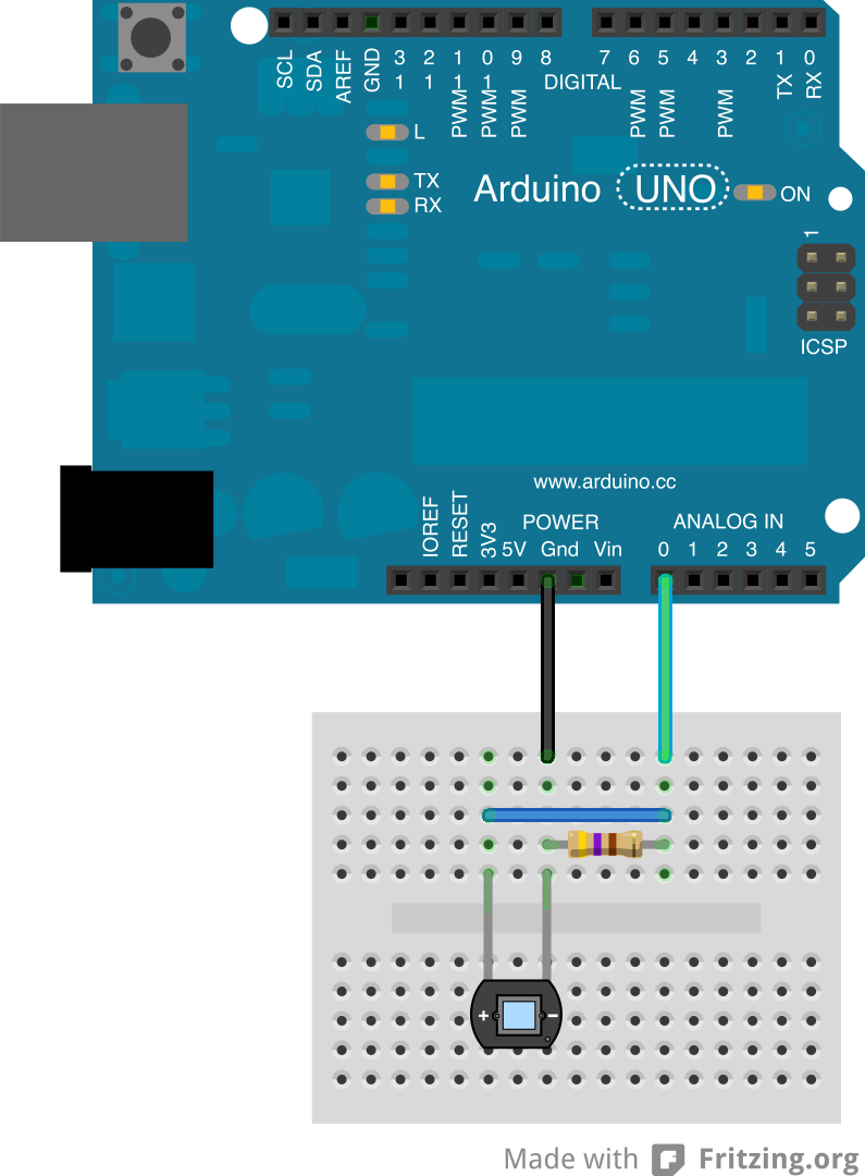
I found different designs how to plug the diode in the op_amp, which is a LM358 and came up with the circuit attached.
However, values reach from 50 to 100, which doesn’t make sense. What am I doing wrong?
Thanks for your help!

Well first of all your schematic is wrong: there's no OpAmp drawn in there. Just some square thingy which I guess is your attempt at drawing an OpAmp. I have no idea what you're trying to do there.
Install software like KiCAD for your schematic drawings - it's not hard to learn the basics of it and will help you a lot drawing even simple schematics like this.
Photo diodes tend to be most sensitive to IR, so unless you want to measure IR (there's a lot of that in sunlight) and not visible light, they're not the right tool for the job.
An LDR would work a lot better already, those are more sensitive to visible light and can be wired as simple voltage divider. With the resistance of the LDR varying from <100 Ohm to a few MOhm, it's easy to get (almost) full range for your ADC.
LDRs are not the most accurate devices, so if you need to have more accuracy than "dark, not so dark, twilight, light, bright light, full sunlight" you'll have to get a proper brightness sensor such as the TSL2561 or it's successor the TSL2591. They give you the absolute lux brightness value.
I can see what he has done in his drawing. Looks like an 8 pin DIP to me. He is showing the pins of the opamp and how he has it wired.
I don't know how you connected the photodiode without the opamp, and I'm afraid it is damaged. But time will tell as you move through the next few items.
You will need to back up to the basics. The photodiode does not produce a voltage, but only allows current to pass in proportion to the light detected. Simple sensors work in fire-triangle. Instead of fuel, oxygen, and ignition source. You need (1) power, (2) ground, and (3) output. The photodiode is only a two-pin device, so how do you make three connections? Answer, add a resistor. The resistor will also serve to protect the photodiode from too much current when the light is brightest. I suggest to connect the diode to power and the resistor and the resistor to ground. Now you have (1) power, (2) output at the diode resistor junction, and (3) ground. Connected in this manner the output will be 0V when dark and close to power voltage when fully bright.
The resistor should be chosen to not exceed the current rating of the photodiode, ohms = current rating divided by power supply.
With this, you should not need the opamp. I'm not sure the LM358 will work in your application anyway. The datasheet shows a Voh of 26 for a power supply of 30V. The output is not rail-to-rail and appears to stop at worst 4V from the power supply. Which with a 3.3V supply, doesn't work well.
Could very well be - anyway it left me guessing and I'm not about to start digging up spec sheets to see how the OpAmp is hidden inside that black box (as that's what a DIP packing rather literally is), and it's not a proper schematic anyway. More like a wiring diagram (which is helpful but only after making the schematic).
Thanks for your answers. I'm trying to make things clearer and include a better diagramm as my horrible drawing ![]()
Without the op-amp, I connected the photodiode as described here, using a resistor of 30 Ohms. In the data sheet provided by TI it's said that 3.0V are sufficient as supply voltage (link). The photodiode I'm using should be sensitive between 350 nm and 1150 nm. The general idea is to make a PAR sensor, similar as described here, using a IR-UV cut filter.

What resolution do you need? Why are you using an op-amp? Do you know what an op-amp does? Have you hooked up the photodiode 'correctly', and therefore incorrectly? Is it supposed to work in reverse for better sensitivity?
sojaman:
Without the op-amp, I connected the photodiode as described here, using a resistor of 30 Ohms.
Euhm... that's a diode and a resistor in parallel between an analog in and GND. It doesn't make any sense to me. That will measure 0V all the time, no matter the lighting.
The general idea is to make a PAR sensor, similar as described here, using a IR-UV cut filter.
Interesting project, but while they mention PAR it's not what they're doing. Photosyntheses has two peaks, around 400 and around 700 nm, and the 500-600 nm spectrum is not used. So the flat response is already wrong for PAR.
The first two articles there talk about getting that light sensor to work, but nothing after that, and the response graphs shown are not exactly promising. I also really don't know what this convoluted contraption could possibly do what a much cheaper, much smaller and much more accurate TSL2591 chip can not (that chip is about 3x3 mm so even smaller than the photodiode in this article, and no need for all those external components).
No-one has so far made a working PAR sensor based on Arduino, as far as I can tell after many hours of google searches and reading forums about the subject. I haven't been able to find many PAR sensors at all - and those that are available are expensive. Very expensive.
If you want to measure PAR with direct sunlight, no problem. Just use a brightness sensor, you know the exact spectrum so it's an easy calculation. But in ANY other light situation your measurements will be off as for PAR you have to do a complete spectrum analyses. Even three-channel RGB with well known response on each sensor is not good enough - that works maybe for other outdoor light situations and some artificial light (with known, continuous spectra), but completely breaks down under LEDs (which emit rather specific wavelengths), and other situations where a PAR sensor rather than a simple brightness sensor is what you really want.
Euhm... that's a diode and a resistor in parallel between an analog in and GND. It doesn't make any sense to me.
That circuit is using the photodiode in photovoltaic mode, and it is perfectly valid. The current generated by the diode develops a voltage across the resistor, approximately proportional to the light intensity.
Bsr à tous.
Je travaille sur le même sujet mais plutôt avec un phototransistor.
Mon problème se situe au niveau de l'amplification et du filtrage du signal.
En plus comment faire un code qui va me donner le résultat en w/m2 ?
Merci
I will use the sensor only with sunlight (underwater though, which shifts the spectrum a bit), so I want to have a simple light sensor and would therefore use the diode with amplified signal. However, with the present circuit, values change only between 75 and 100, meaning a lower resolution than without the amplifier. What is wrong in the current op-amp setup?
I can't make any sense of your diagram, so anything could be wrong with the amplifier circuit. You should be using an appropriate circuit and very importantly, an op amp suitable for single supply operation, rail to rail output at 3.3V. The LM358 is not one of those.
To get higher resolution with the photodiode/resistor combination, just use the 1.1V internal reference for the ADC.
A (BPW20RF) photo diode should work ok in photovoltaic mode (directly connected to an analogue pin and ground) with 1.1volt Aref enabled. But not with a 30 ohm load resistor (post#4).
Try 100k.
Leo..
A photo diode is not normally used in photovoltaic mode.
You measure the current flowing with either 0V across the diode or with it reverse biased.
The (unloaded) forward voltage is both a very coarse indication of the photocurrent (sometimes useful if
you want a logarithmic response (*)), but sensitive also to the temperature, which is not useful.
Photocurrent is essentially proportional to illumination and unaffected by temperature. It is best
measured at 0 bias or reverse bias (faster response).
(*) This would be a good way to distinquish starlight/moonlight/room lighting/sunlight levels, but not
for any accuracy.