Hi. I'm trying to understand if it's possible to measure the remaining power in batteries with Nano 33 IoT. My power requirement is one HC-SR04 sensor (3,3V version) taking a reading say every 3 minutes, then sending this data via WiFi (I need to use WiFi). As I understand I have 2 options:
use 18650 battery pack with USB
use a battery holder with say 4 AA batteries connected to VIN
For simplicity's sake I would like to use option 1) as then I can insert another battery pack more easily than with the Dupont cables. I've read through the subcategory of Nano 33 IoT - Arduino Forum and I can't find any concrete answers.
One more important clarification - if at all possible, I'd like the solution not to involve extra hardware (resistors etc). As I understand some other boards have internal components that one could use to calculate the remaining power, but not the Nano 33 IoT?
So one Nano 33 IoT board, battery holder with 4xAA batteries/USB charging pack with 2 LiPo batteries, one HC-SR04 (3,3V) sensor. Is it possible to check the level of power remaining in the batteries (without extra/added hardware)?
What do you mean? I'm not proficient in reading the schematic on that level, but furthermore I don't get the point of checking for the mentioned components connected to the VIN? Perhaps I explained my problem badly, but I don't get what you're saying here.
It's possible to get an rough estimate of the remaining battery power by measuring its voltage level.
The bottom line is that to do this you'll need to reduce maximum voltage you expect the battery pack to produce down to 3.3V or less using a resistive voltage divider, so that it can be measured using one of the microcontroller's analog inputs.
For example, if you take a look at the Arduino MKR boards, they measure the voltage of a single cell Lipo. The maximum expected voltage of a fully charged single cell Lipo is 4.2V. They use a 330K and 1M2 resistive divider to reduce the voltage down to 3.29V:
Vout = 4.2V * 1M2 / (330K + 1M2) = 3.29V
Since these resistor values are large to reduce power comsumption for battery powered applications, the source impedance into the ADC input is too high to drive ADC's input, (or in other words charge the ADC's sample capacitor), so a trick is used to effectively lower source impedance by connecting an additional 100nF reservoir capacitor at the ADC input. A good explaination/discussion can be found here:
It is possible to measure the battery voltage on an Arduino Nano 33 IoT using a resistor potential diver as stated by MartinL above, connected to the Nano 33 IoT's analog inputs.
However, the Nano 33 IoT really isn't suitable for a battery-powered environment because it has
very limited sleep capabilities & consumes way too much power when it's just sitting there doing nothing! It would be far better for you to use an ESP32 which has very good sleep capabilities in a battery-powered environment.
For example, I have a setup using an ESP32 that wakes up every 600 seconds & collects - Temperature, Humidity, Pressures, and Sea level pressure including battery Voltage & calculating the battery % left. It then sends all this collected data to the Arduino cloud, it also some of that data out via an nRF24L01 radio, then it goes back to sleep for 600 seconds. I'm powering this from a high capacity 13400mAh lithium-ion battery pack plugged straight onto the ESP 32 I'm getting well over a month between chages. Although I don't use the ESP 32 inbuilt battery charger like this is only a 500mAh charge rate & takes forever to charge a 13400mAh battery pack.
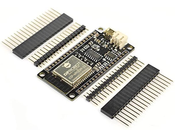
The ESP32 I'm using that is supported by the Arduino IoT cloud & has battery connection capabilities including an inbuilt resistor potential diver already connected to an analog port is THIS one.
Hi @robrs
This is an extremely interesting proposal it does seem like a much better alternative. The main reason I was looking into the Nano 33 IoT was the price/value/size ratio, but the FireBeetle ticks all the boxes but one - is there something similar with headers? I'd like to avoid soldering if possible. Or if you're able to reference some other alternatives I'd be very grateful. I did try to Google it (best board to use etc), but it seemed like the information is quite scant or my google-fu is not that strong
The FireBeetle is supplied with the following headers -
You would just need to solder the pin header on. If you are not confident in soldering the pin header in place, is there a mate you could ask to help with this?
I'll manage Any chance you could share your code for the sleep and battery part? I've read the examples for the VIN, but as you already seem to be powering it from USB (I'm guessing?) and my example was with the Nano, then it would be really helpful.
No, I'm powering the ESP32 FireBeetle from a lithium-ion battery pack plugged into the ESP32's 2 pin JST-PH connector.
The code below should help you on your way?
The code will monitor (Once per set of loops) the battery voltage (via analog port 0 of the ESP32 FireBeetle), and calculate the Battery % left of a Battery connected to the 2 pin JST-PH connector.
It will then upload the Battery voltage & Battery percentage to the Arduino IoT cloud, then the ESP32 will go into Hibernation for 600 seconds & then starts up again.
I've also left commented out Debug messages & Code references, please feel free to remove them once you have it up & running.
The code -
/*
  Sketch generated by the Arduino IoT Cloud Thing "Outside_Stats"
  https://create.arduino.cc/cloud/things/*******************************

  Arduino IoT Cloud Variables description

  The following variables are automatically generated and updated when changes are made to the Thing


  float voltage;
  int bat_percentage;

  Variables which are marked as READ/WRITE in the Cloud Thing will also have functions
  which are called when their values are changed from the Dashboard.
  These functions are generated with the Thing and added at the end of this sketch.
*/


#include "thingProperties.h"

// Mathematical functions library used for roundf function
#include <math.h>


// Variables used for Battery monitor
int analogInPin  = A0;    // Analog input pin
int sensorValue;
float calibration = 0.22; // Check Battery voltage using multimeter & subtract the Battery voltage shown in the Serial Monitor


// Variables used for for millis time delay
int period = 2500;
unsigned long time_now = 0;

//  Variable used for setting an initial loop count.
int loopcount = 0;


// Definitions used for ESP32 sleep period
#define uS_TO_S_FACTOR 1000000  //Conversion factor for micro seconds to seconds
#define TIME_TO_SLEEP  600     //Time ESP32 will go to sleep (in seconds)


// MAIN SETUP

void setup() {
  // Initialize serial and wait for port to open:
  Serial.begin(9600);

  // This delay gives the chance to wait for a Serial Monitor without blocking if none is found
  delay(1500);

  // Defined in thingProperties.h
  initProperties();

  // Connect to Arduino IoT Cloud
  ArduinoCloud.begin(ArduinoIoTPreferredConnection);

  /*
     The following function allows you to obtain more information
     related to the state of network and IoT Cloud connection and errors
     the higher number the more granular information you’ll get.
     The default is 0 (only errors).
     Maximum is 4
  */
  setDebugMessageLevel(4);
  ArduinoCloud.printDebugInfo();


  //configure ESP32 sleep
  esp_sleep_enable_timer_wakeup(TIME_TO_SLEEP * uS_TO_S_FACTOR);
  // configure ESP32 hibernation
  esp_sleep_pd_config(ESP_PD_DOMAIN_MAX, ESP_PD_OPTION_OFF);
  esp_sleep_pd_config(ESP_PD_DOMAIN_RTC_PERIPH, ESP_PD_OPTION_OFF);
  esp_sleep_pd_config(ESP_PD_DOMAIN_RTC_SLOW_MEM, ESP_PD_OPTION_OFF);
  esp_sleep_pd_config(ESP_PD_DOMAIN_RTC_FAST_MEM, ESP_PD_OPTION_OFF);

}


// MAIN LOOP

void loop() {

  // Check for IOT connection
  while (ArduinoCloud.connected() == 0)
  {
    ArduinoCloud.update(); //required so things don't crash on us
  }

 // Serial.println("Connection to IoT Cloud \r");


  // Update Arduino IoT Cloud - run multiple times to cut down on loops!
  ArduinoCloud.update();
  ArduinoCloud.update();
  ArduinoCloud.update();
  ArduinoCloud.update();


  // request sea level pressure form OpenWeatherMap


  // read temperture, humidity, pressure & calculate Heat index


  // read battery status
  batterystatus();

  // Increment the loopcount
  loopcount++;

 // Serial.print("\r Loopcount = "); Serial.print(loopcount); Serial.print("\r");

  time_now = millis();
  while (millis() < time_now + period) {
  }

  // Check the loopcount
  if (loopcount == 7) {         // Exit if loopcount =

    // disconnect WiFi
    WiFi.disconnect(true);


    // Send 2.4G radio data


   // Serial.print("\r Going to sleep..... \r");


    //Send ESP32 to sleep now
    esp_deep_sleep_start();

    // We never arrive here because the ESP32 was put to sleep
    while (1);

  }
}


// Capture the current battery status

void batterystatus() {

  // Only run the code if loopcount = 0
  if (loopcount == 0) {

    sensorValue = analogRead(analogInPin);
    voltage = (((sensorValue * 3.3) / 1024) * 0.5 + calibration); //multiply by 0.5 as voltage divider network is 1M & 1M on ESP32 FireBeetle

  }
  // Round off (Voltage) to 2 decimal places
  voltage = (roundf(voltage * 100.0) / 100.0);

  bat_percentage = mapfloat(voltage, 3.6, 4.1, 0, 100); //3.6V as Battery Cut off Voltage & 4.1V as Maximum Voltage

  if (bat_percentage >= 100)
  {
    bat_percentage = 100;
  }
  if (bat_percentage <= 0)
  {
    bat_percentage = 1;
  }

  // Serial.print("\r Analog Value = ");
  // Serial.print(sensorValue);
  // Serial.print("\t Battery Voltage = ");
  // Serial.print(voltage);
  // Serial.print("\t Battery Percentage = ");
  // Serial.println(bat_percentage); Serial.print("\r");

}

float mapfloat(float x, float in_min, float in_max, float out_min, float out_max)
{
  return (x - in_min) * (out_max - out_min) / (in_max - in_min) + out_min;

}
Please Note: The No. of loops & Millis delay has been set to achieve reliable updates of the Arduino IoT cloud. Reducing either the No. of loops or the Millis delay will have an effect on the reliability of the updates!
Oh yes, one other thing to note with the ESP 32 FireBeetle is they did not fit a couple of 0-ohm resistor links to enable the Battery monitoring via Analog port 0 !!
The photo below shows where a couple of solder links need to be added between the green arrows -
just to be clear: float calibration = 0.22; // Check Battery voltage using multimeter & subtract the Battery voltage shown in the Serial Monitor <- so I should check my battery voltage with a multimeter before connecting it to the Firebeetle, record the value then start this code and see what is shown in the Serial monitor? You mean this part:
// Serial.print("\t Battery Voltage = ");
// Serial.print(voltage);
if I'm reading it right, I can use either the JST-PH connector or the USB connector for the battery pack? Would the code remain the same? I can't figure out where you get the information for it, from A0?
1. All battery measurements should be done with the battery connected to the ESP32 & the code running.
Yes, just uncomment the two lines below & read the voltage output on the Serial monitor - IoT Cloud > Thing > Sketch > Open full editor > Monitor
// Serial.print("\t Battery Voltage = ");
// Serial.print(voltage);
2. The inbuilt potential resistor divider on the ESP32 will only measure (When the links have been inserted as previously shown) the battery voltage of a battery connected to the JST-PH connector NOT the USB connector. You would have to set up an external potential resistor divider, not insert the links previously shown & connect the output of the external potential resistor divider to A0.
See the first page of the ESP 32 FireBeetle Schematic & you'll see the inbuilt potential resistor divider connected to VB, GND & A0 You will also that the USB 5V is not monitored!
3.THIS is the battery pack I'm using. Although the battery pack you are proposing to use only has a 2.2A capacity, depending upon the devices you connect to the ESP32 & the sleep period you employ, I'm not sure what serviceable life you will get out of that battery pack between charges?
For example, after 35 days since my last charge, my battery has only dropped by 40%
I can't find the power consumption for the 3,3V option that I have, but for example let's assume (from this Turn power on and off to ultrasonic sensor (HC-SR04) - #18 by Sakibjoy123) that "My HC-SR04 has a peak of 15 mA as it turns on, and then it consumes 6 mA" so the draw would be:
15mA + 6mA ~ 21mA per each run
so 20 times per hour
that means 20 x 21mA = 420mA per hour
so 10A per day
Fair enough. For my example it would be board boot time + one reading from the sensor. For the Nano IoT 33 it was fairly quick I think, a couple of seconds maybe? So let's take the example of 20 times an hour for 10 seconds each time, how would that work out? With the same current draw I posted above.
@robrs I managed to get the code working and the resistors in place (I think :)) These are the results I'm getting (picture from Thingsboard, not serial):