Measuring Temperature using Thermocouples

Hey Guys,

so I have an Application where I want to measure temperatures roughly between room temperature and 500°C at two different points. I have searched the Internet which recommended Type K Thermocouples.

So I went ahead and bought 2 and for each a Max31855 Controller.

Now the issue is getting both to run at the same time.

Right now my setup consists of a Breadboard, 2x max31855, 2x thermocouple type k, a Arduino uno and a 1602 LCD Keypad Shield plugged into the Arduino (all the Pins are soldered into the Shield).

I am running the Sensors via 3.3V, which they both get from the Arduino (and GND back).

Over the Breadboard I am connecting the thermocouples to 5 Pins of the Arduino.

For the Code I am running the following:

/***************************************************
  This is an example for the Adafruit Thermocouple Sensor w/MAX31855K

  Designed specifically to work with the Adafruit Thermocouple Sensor
  ----> https://www.adafruit.com/products/269

  These displays use SPI to communicate, 3 pins are required to
  interface
  Adafruit invests time and resources providing this open source code,
  please support Adafruit and open-source hardware by purchasing
  products from Adafruit!

  Written by Limor Fried/Ladyada for Adafruit Industries.
  BSD license, all text above must be included in any redistribution
 ****************************************************/

#include <SPI.h>
#include "Adafruit_MAX31855.h"

// Default connection is using software SPI, but comment and uncomment one of
// the two examples below to switch between software SPI and hardware SPI:

// Example creating a thermocouple instance with software SPI on any three
// digital IO pins.
#define MAXDOO   A4
#define MAXCSO   A5
#define MAXCLK  A3
#define MAXDOU   A2
#define MAXCSU   A1


// initialize the Thermocouple
Adafruit_MAX31855 thermocoupleU(MAXCLK, MAXCSU, MAXDOU);
Adafruit_MAX31855 thermocoupleO(MAXCLK, MAXCSO, MAXDOO);

void setup() {
  Serial.begin(9600);

  while (!Serial) delay(1); // wait for Serial on Leonardo/Zero, etc

  Serial.println("MAX31855 test");
  // wait for MAX chip to stabilize
  delay(500);
  Serial.print("Initializing sensor...");
  if (!thermocoupleO.begin()) {
    Serial.println("ERROR. Oben");
    while (1) delay(10);
  }
  Serial.println("DONE.O");
  if (!thermocoupleU.begin()) {
    Serial.println("ERROR. Unten");
    while (1) delay(10);
  }
  Serial.println("DONE.U");
}

void loop() {

  double co = thermocoupleO.readCelsius();
  if (isnan(co)) {
    Serial.println("Something wrong with thermocoupleo!");
  } else {
    Serial.print("Co = ");
    Serial.println(co);
  }

  delay(1000);
  
  double cu = thermocoupleU.readCelsius();
  if (isnan(cu)) {
    Serial.println("Something wrong with thermocoupleu!");
  } else {
    Serial.print("Cu = ");
    Serial.println(cu);
  }

  delay(1000);
}

This is basically the Adafruit Code, but changed so that its actually using 2 Thermocouples.

If I run this Code, one thermocouple often throws error codes (when not, it will actually give the correct temperature). The Second Termocouple only measures 0°C.

Keep in mind, the Thermocouples are not connected to anything, they are just loosely laying on the ground.

If I disconnect the Power supply of one Thermocouple controller, the Measurements seem to work, but also very unreliably

Does anyone know what is going on? I have no clue why one is reading fine (well not even that) and the other is not working at all?

BTW. If anyone can suggest any other ways/sensors to measure these high temperatures, id be open to anything.

TL;DR: I cannot get 2 thermocouples to work

1 Like

Is there any difference if you use different CLK pins for each MAX31855K?

1 Like

No

The only thing I noticed is that the 5v/3.3V has a big influence on it. Basically, the thermocouple will only read values if its plugged straight into the arduino (either direct or over the 1602 Shield, doesnt matter).

The Layout/which Pin I use for CLK/CS/DO doesnt matter really ( I have found).

But if I plug the 5v into the breadboard and the 5v from the Arduino into the Breadboard, the Sensor wont read anything (0°C)

1 Like

This isn't clear. What exactly is the first "5v"? The sensor VCC pin?
Same for the second "5v". Is that the 5V output pin of the Arduino?

This datasheet says to use 3.3V for the sensor VCC. The signal levels are also directly related to that.
The Arduino UNO is a 5V device, so you'll need some signal level shifter.

For a type K thermocouple you should use the MAX31855K version.
Also, don't skip the capacitor between VCC and GND.

Try to get just one of the sensors to work reliably, then you can add the second.

1 Like

To start out, I have to say that I managed to get the Setup to run. This is definetely far from optimal (or even usable right now but I might have to figure something out) but if I use an Independent Power Pin for each Sensor (I also have to power a Relay so its not easy) it actually works.

So now I am using:
VIN -> Thermocouple 1
5V -> Thermocouple 2
3.3V -> Relay (its actually a 5v relay but it seems to work, the status lights are just a bit dimmer).

The first Time I ran this, everything seemed to work perfectly. No Error Measurements, the relay worked, everything was fine.

In the Meantime, I have found out that its actually a terrible Idea to use the VIN Pin. It seems like the Max31855 which was plugged into it has died because of overvoltage (there is a noticeable swelling on a Chip and the Device has started to smell terribly).

I am unsure why, or if this was the only cause of its death as I started to power the Arduino with the USB over my laptop (which is always 5v right?). The second time I ran it, there were constant error Messages in both thermocouples. I thought, maybe the Arduino doesnt have enough Power and I plugged into my Arduino Power Supply (9V). I am guessing that the VIN Output will Output whatever Voltage it uses to power the Arduino. So the Arduino switched to 9V, which seemed to be a bit too much for the MAX31855.

Can I even use the VIN for Power Output long term? Would it work if I only use a 5v Power Suply?

I have a 5V transformer which I want to actually use to power everything, but the Sensors dont want to read anything unless they are powered directly by the Arduino. Because I just tried it out and the Transformer will actually power the relay, but if I plug the Sensors into it, the Sensor will just read 0 (I just tried one for now since the other one is dead).

Sorry, the first 5v is the VCC from the first max31855, the second 5v is the Arduino Output.

hmmmmmm

I am unsure about your Datasheet. I have thought about the possibility of the Voltage being wrong (see the dead thermocouple lol), but I think that the Datasheet of yours only relates to the Maxim Integrated Max31855, which looks like this:

but mine is the standard china Max31855K (I checked, its the K Type) like this:

and according to the ebay seller (in the article I posted earlier), it takes everything from 3-5V. So I should be fine using either 3.3 or 5V.

Now I thank you for the Feedback regarding the Capacitor, I just ordered some so I can solder/fix this ( I mean I also have to order another Max31855k now.... )

Sorry that my reply took so long and is so broken up, I have continued experimenting and figured out some stuff along the way.

1 Like

Hmm, the only link i see in your initial post is the one within the code - https://www.adafruit.com/products/269
That module has a lot more (visible) parts than the one in your last picture.

Compare the two:


I found this, is that the same you have?
Either the pictures or the description appear to be wrong - there is no voltage regulator, no level shifting circuitry, only the chip and a bypass capacitor.

1 Like

I use the MAX31855 in a data logging application. I didn't use any library but read direct. Adafruit libraries are very capable but sometimes they seem to be to too want to use C++ objects for simple devices in simple programs.

The attached code is for an Arduino M0 (32 bit) but can easily be used in a 8bit Arduino by changing the interrupt syntax.

You should but the Clock and Data lines on the "std" Arduino SPI lines. Then put the CS\ 's on different pins. Remember CS\ is active low so both CS lines should be high then bring each low (one at a time) to read the device.

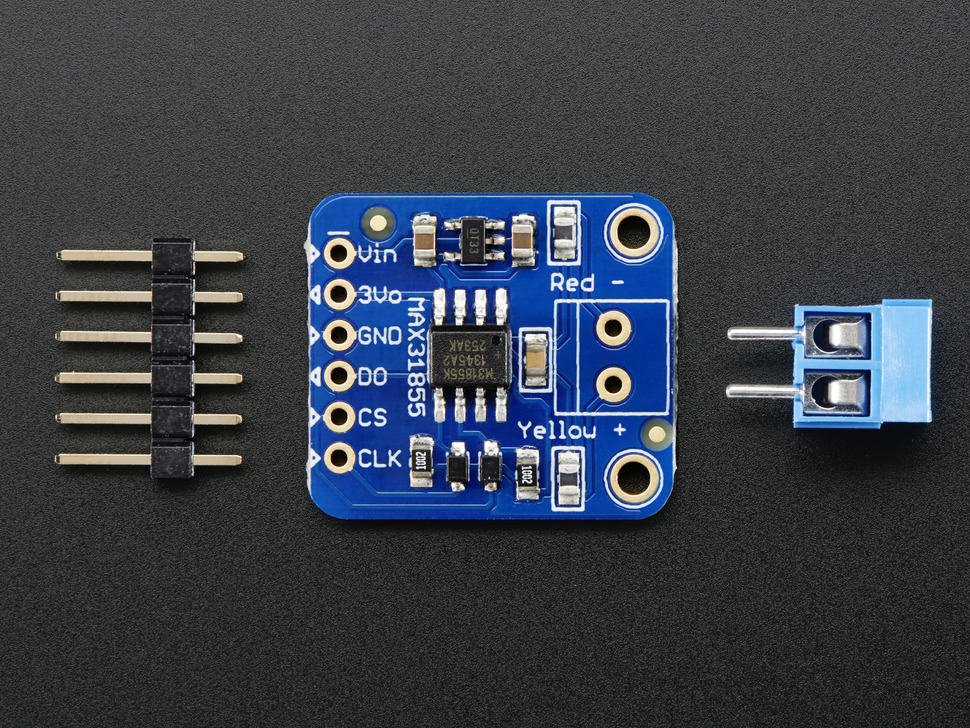
My board that looks like post #6 has a regulator. This board is by far superior as the two gray SMD parts on right side are inductors, they aid in filtering out noise.


   EIC Interrupt Control:
  	   EIC->CTRL.bit.ENABLE = 1;   and   	EIC->CTRL.bit.ENABLE = 0;

  Target Processor / Board:
   WeMos SAMD21 M0 – a Variant of the Arduino M0


   Hardware Description:
	 1) MAX31855k,4 SPI, performs conversion when CS goes high, No library req'd
	 2) SD Card, SPI,  caution some boards don't tri-state MISO,   SDFat library
	 3) DS3132 RTC,        No library required.
	 4) OLED 128 x 32      ASCII1306 Library
*/

#define VERSION "Ver: RC13"
#define DEBOUNCE 2
//#define DEBUG

#include <Wire.h>
#include <SPI.h>	// SD Card & TypeK
#include "SdFat.h"
SdFat SD;			// keep existing code that used SD but still use the SdFat library

// OLED
#include "SSD1306Ascii.h"
#include "SSD1306AsciiWire.h"

#include "FurnaceApp.h"

// *** declare Functions Prototypes ********************************************
// ***************************************************************************
void init_pins_int(void);
void initSD_Card(void);
void init_RTC(void);
void init_TypeK(void);
void init_OLED(void);
uint16_t ReadRawTemperature(void);
void ConvertSectoHour(int32_t n);
void WriteDataSD(void);
void WriteFileHeader(void);

// *** declare Objects *******************************************************
// ***************************************************************************
File myFile;			// create instance of a "File" class for SD Card
SSD1306AsciiWire oled;	// create an "oled" object

// *** declare gVariables ****************************************************
// ***************************************************************************
int16_t hour;
uint8_t minute;
uint8_t second;

byte ourInputs[] = {BurnerPin, CircPin, AquaPin, Level1Pin, Level2Pin, Level3Pin};
// pin # assignments   1          3        5         6         7           8
#define NUMINPUTS sizeof(ourInputs)
uint8_t Data[NUMINPUTS], prevData[NUMINPUTS], delayCnt[NUMINPUTS];
bool LogData = false;   // goes true on input change resulting in the data written to SD

// *** Setup  ****************************************************************
// ***************************************************************************

void setup() {

	SerialUSB.begin(115200);
	delay(1000);
	SerialUSB.print(".....starting    ");
	SerialUSB.println(NUMINPUTS);
   EIC->CTRL.bit.ENABLE = 0;  // hold off any interrupts until setup complete.
   init_pins_int();

   // start I2C...
   Wire.begin();
   Wire.setClock(100000UL);

   SPI.begin();  // not sure if this is needed for SD card?

   // *** init Devices <<<<<<<<<<<<<<<<<<<<<<<<<<<<<<<<<<<<
   init_TypeK();
   initSD_Card();
   init_RTC();
   WriteFileHeader();
   init_OLED();
   // update display temperature here ??

   EIC->CTRL.bit.ENABLE = 1;
}  // --- setup ---

uint32_t oldMillis = 0;  // aka "unsigned long"

// ***************************************************************************
// *** MAIN loop *************************************************************
// ***************************************************************************

void loop() {

   if (millis() >= oldMillis + 100)
   {
      for (uint8_t i = 0; i <= NUMINPUTS-1; i=i+1)
      {
         // -----------------------------------------------------------
         if (delayCnt[i] == 0)	// no pending test                   |
         {
            Data[i] = digitalRead(ourInputs[i]);
            if (prevData[i] != Data[i]) delayCnt[i] = 2;
         }
         else
         {
            --delayCnt[i];
            if (delayCnt[i] == 0)
            {
               Data[i] = digitalRead(ourInputs[i]);
               if (Data[i] != prevData[i]) LogData = true;  prevData[i] = Data[i];
            }
         }  //  --- else ---                                         |
         // ----------------------------------------------------------
      }  // --- for ---

      if (LogData) {
         WriteDataSD();
         LogData = false;
         ++logCount;
         oled.SSD1306Ascii::setCursor(11*8,0); oled.print(logCount);
      }

      oldMillis = millis();
   } // -- 100 millis --

   if (gDisplaySeconds >= displayUpdate)
   {
      gDisplaySeconds = 0;
      UpdateDisplay();
   }

}  // --- loop


// ************************************************************
// *** interrupt routine(s) *************************************
// ************************************************************

void ispSeconds() {
   ++SQWseconds;
   ++gDisplaySeconds;
}

// **********************************************************************
// *** functions ********************************************************
// **********************************************************************
// *                                                                    *
// *                                                                    *
// **********************************************************************
// *** Functions ********************************************************
// **********************************************************************

// RTC communication  ------------------------------------------------------------------
uint8_t I2C_readByte(const uint8_t addr) {
   uint8_t data;
   Wire.beginTransmission(RTC_ADDRESS);
   Wire.write(addr);
   Wire.requestFrom(RTC_ADDRESS, (uint8_t)1);
   data = Wire.read();
   RTC_Error = Wire.endTransmission();  //returned status; 0 = success
   return data;
} // readByte()

//--------------------------------------------------------------------------------------
void I2C_writeByte(const uint8_t addr, const uint8_t data) {
   Wire.beginTransmission(RTC_ADDRESS);
   Wire.write(addr);
   Wire.write(data);
   RTC_Error = Wire.endTransmission();
} // writeByte()

//--------------------------------------------------------------------------------------
void UpdateDisplay(void)
{
   uint16_t RTemp;
   RTemp = (ReadTemperature() >> 2) * 0.25;
   oled.SSD1306Ascii::setCursor(0 * 8, 0);
   if (RTemp < 100)  oled.print(" ");
   oled.print(RTemp);
   oled.SSD1306Ascii::setCursor(0 * 8, 2);
   oled.print("SRT");
   oled.print(SD_Error);
   oled.print(RTC_Error);
   oled.print(TypeK_Error);
   ConvertSectoHour(SQWseconds);
   oled.SSD1306Ascii::setCursor(8 * 8, 2);
   oled.print(hour);
   oled.print(":");
   if (minute < 10)  oled.print("0");
   oled.print(minute);
   oled.print(":");
   if (second < 10)  oled.print("0");
   oled.print(second);
}

//--------------------------------------------------------------------------------------
uint16_t ReadTemperature(void)
{
   EIC->CTRL.bit.ENABLE = 0;
   	uint16_t _rawData = 0;
   	SPI.beginTransaction(SPISettings(1000000, MSBFIRST, SPI_MODE0));
   	digitalWrite(TK_CSPin, LOW);       //set CS low to read SPI interface
   	_rawData = SPI.transfer16(0x0000);   // TypeK is read only, doesn't matter what is sent in SPI.transfer16(0x000)
   	digitalWrite(TK_CSPin, HIGH);    // de-select and start a new conversion to be read the next time through
   	SPI.endTransaction();
//   	SerialUSB.println(_rawData);   //  for debug only
   EIC->CTRL.bit.ENABLE = 1;
   TypeK_Error = false;
   if (_rawData & 0b01)
   {
   	 TypeK_Error = true;
   	 _rawData = 0;
   }
   return _rawData;
}

//--------------------------------------------------------------------------------------
void WriteDataSD(void)               //----------------------------------------------***
{

#ifdef DEBUG
		SerialUSB.print(!Data[0]); 	SerialUSB.print(",   ");
      SerialUSB.print(!Data[1]); 	SerialUSB.print(",   ");
      SerialUSB.print(!Data[2]); 	SerialUSB.print(",   ");
      SerialUSB.print(!Data[3]); 	SerialUSB.print(",   ");
      SerialUSB.print(!Data[4]); 	SerialUSB.print(",   ");
      SerialUSB.println(!Data[5]);
#endif

   EIC->CTRL.bit.ENABLE = 0;
   myFile = SD.open(gDataFile, FILE_WRITE);
   if (myFile)
   {
      myFile.print(SQWseconds); 			myFile.print(", ");
      myFile.print((ReadTemperature() >> 2) * 0.25); myFile.print(", ");

      myFile.print(!Data[0]); 	myFile.print(", "); // Burner
      myFile.print(!Data[1]); 	myFile.print(", "); // Circulator
      myFile.print(!Data[2]); 	myFile.print(", "); // Aquastat
      myFile.print(!Data[3]); 	myFile.print(", "); // Level 1
      myFile.print(!Data[4]); 	myFile.print(", "); // Level 2
      myFile.println(!Data[5]);  // Level 3
      myFile.close();
   }  // if (myFile),  Loop time was: 18 ~ 19 ms with a few at 25 ms
   else
   {
      SD_Error = true;  // --- if (myFile) else
   }

   EIC->CTRL.bit.ENABLE = 1;
}  // WriteDataSD

//--------------------------------------------------------------------------------------
// function convert second into hour minutes seconds
//--------------------------------------------------------------------------------------
void ConvertSectoHour(int32_t n)
{
   hour = n / 3600;
   n = n % 3600;
   minute =  n / 60;
   n %= 60;
   second = n;
}


// ************************************************************
// *** initialization functions *******************************
// ************************************************************

// --- SD Card initialization function ---
void initSD_Card(void) {
   if (!SD.begin(SD_CSPin)) {
      SD_Error = true;
   }
   // loop until we find a file that doesn't already exist.......
   do
   {
      itoa(gFileNumb, gDataFile, 10);  // (value, Array, base)
      const char *extension = ".csv";
      strcat(gDataFile, extension);  // syntax:  strcat(dest, source)
      ++gFileNumb;
   } while (SD.exists(gDataFile));  // assume will Rtn false if  no communication.

   myFile = SD.open(gDataFile, FILE_WRITE);
   if (myFile) {      // if the file opened okay, write to it:
      myFile.print(" init...");
      //myFile.println(gDataFile);
      myFile.close();
   }
   else {
      SD_Error = true;   // if the file didn't open, print an error:
   }
   return;
}  // --- initSD_Card ---


//--------------------------------------------------------------------------------------
void init_RTC(void) {
   gReg0x0F = I2C_readByte(RTC_0F);		// (address, data)
   if (gReg0x0F & 0b10000000)  // test OSF bit
   {
      RTC_Error = true;
   }
   else
   {
      I2C_writeByte(RTC_0E, 0x0);
      I2C_writeByte(RTC_0F, 0x0);
   }
}  // --- init_RTC ---

//--------------------------------------------------------------------------------------
// --- furnace setup function ---
void init_pins_int(void) {
   // Setup CS pins first....
   pinMode(TK_CSPin, HIGH);  	// enables pull-up immediately keeping pin high
   digitalWrite(TK_CSPin, HIGH);
   pinMode(SD_CSPin, HIGH);
   digitalWrite(SD_CSPin, HIGH);
   pinMode(ledPin, OUTPUT);

   pinMode(Level3Pin, INPUT_PULLUP);
   pinMode(Level2Pin, INPUT_PULLUP);
   pinMode(Level1Pin, INPUT_PULLUP);
   pinMode(AquaPin, INPUT_PULLUP);
   pinMode(CircPin, INPUT_PULLUP);
   pinMode(BurnerPin, INPUT_PULLUP);
   pinMode(intSQWPin, INPUT);

   attachInterrupt(digitalPinToInterrupt(intSQWPin), ispSeconds, RISING);
}

//--------------------------------------------------------------------------------------
void init_TypeK(void)
{
   // doesn't really initialize, simply reads the error bit
   int16_t _rawData = 0;
   digitalWrite(TK_CSPin, LOW);       //stop  measurement/conversion
   delayMicroseconds(1);
   digitalWrite(TK_CSPin, HIGH);      //start new measurement/conversion
   delay(100);
   SPI.beginTransaction(SPISettings(1000000, MSBFIRST, SPI_MODE0));
   digitalWrite(TK_CSPin, LOW);       //set CS low to read SPI interface
   _rawData = SPI.transfer16(0x0000);   // TypeK is read only, doesn't matter what is sent in SPI.transfer16(0x000)
   digitalWrite(TK_CSPin, HIGH);    // deselect
   SPI.endTransaction();
   if (_rawData & 0b01) TypeK_Error = true;
   return;
}

//--------------------------------------------------------------------------------------
void init_OLED()
{
   oled.begin(&Adafruit128x32, OLEDADDRESS);
   oled.setFont(ZevvPeep8x16);  // Screen = 4 (0,2,4,6) lines X 16 characters (0 to 15)
   oled.clear();
   oled.print(VERSION);
   delay(5000);
   oled.clear();

   oled.SSD1306Ascii::setCursor(3 * 8, 0);
   oled.print("$C,#Rdg");   // font hacked,  $ prints °
}

//--------------------------------------------------------------------------------------
void WriteFileHeader()
{
   Wire.beginTransmission(RTC_ADDRESS);
   Wire.write(0x00);  // This is the first register address (Seconds)
   // ... read from here 7 uint8_ts
   Wire.endTransmission(false);
   Wire.requestFrom(RTC_ADDRESS, 7);
   uint8_t  ss = bcd2bin(Wire.read() & 0x7F); // why mask 8th bit here?
   uint8_t  mm = bcd2bin(Wire.read());
   uint8_t  hh = bcd2bin(Wire.read());
   Wire.read();                               // day of week, not used
   uint8_t  d = bcd2bin(Wire.read());
   uint8_t  m = bcd2bin(Wire.read());
   uint16_t y = bcd2bin(Wire.read()) + 2000;

   myFile = SD.open(gDataFile, FILE_WRITE);
   if (myFile) {
      myFile.print("DataFile Name: ");
      myFile.println(gDataFile);
      myFile.println();
      myFile.print("Firmware Version:  ");
      myFile.println(VERSION);
      myFile.println();
      myFile.print("Creation Date - Time: ");
      myFile.print(y);
      myFile.print("-");
      myFile.print(m);
      myFile.print("-");
      myFile.print(d);
      myFile.print("  ");
      myFile.print(hh);
      myFile.print(":");
      myFile.print(mm);
      myFile.print(":");
      myFile.println(ss);                          // <-------   ,,,,,,,,,,,
      myFile.println();                            //  or here
      myFile.println("Δ seconds, Temp °C, Burner, Circulator, Aquastat, Level 1, Level 2, Level 3");
      myFile.close();
   }
   else {
      SD_Error = true;
   }
   return;
}

// --- end of code ---

Hi,
Can you please post a circuit diagram of your project?
Hand draw image would be fine.
Can you please post some pictures of your project so we can see your component layout?

I presume you know the K-Type wires, RED is Negative.

Tom... :smiley: :+1: :coffee: :australia:

The ebay seller has no clue. This board has only the Max31855, no other active parts. It is a 3.3V input board because it is a 3.3V IC. See post #6 for what is a superior board (in my view). Also note the I/O lines are still 3.3V. You might get away with a resistor in the CS\ and CLK lines.

2 Likes

I have used those Adafruit MAX31855K modules extensively for years with no problems at all.

1 Like

Have you run with two thermocouple boards? If so you have maybe the OP could glean some information from how your code setup the two boards and what pins you used.

As for my opinion of the Adafruit driver(s). I never suggested they were not usable, I just found for me the few lines of code I needed to read the sensor was much smaller than the Adafruit library. However I will admit I don't have any info of the compiled size of the two approaches.

1 Like

I didn't have any problems with the Adafruit library, but I found another one I like better:

The reason is that it offers status data along with the temperature reading. At least at the time I was evaluating it, the Adafruit library only provided one or the other for each read, which I found more awkward.

2 Likes

Sorry its literally the first circuit I have ever drawn in my life, I'll try to find some software tomorrow which has something resembling the max31855 and a 2 channel relay and I'll draw something digitally

Wow yeah I didnt notice that they look different. In retrospect it was luck but I have the one which I posted, so its the "simple" version with no voltage regulator. So I guess atleast some part definetely comes from the wrong voltage, altough the Issue still persists even if I power both with 3.3V

Wait, so you think the Adafruit Board is superior or the Maxim one ? I have thought about replacing my Boards with the Maxim ones but they are pretty expensive (~20€ per Board)

Im sorry I am unsure about your first question.

Your diagram:

Why do you put the two CLK and DO on separate Arduino pins? They should both be on the same pin. i.e.
Pin xx = CLK1 and CLK2
Pin YY = DO1 and DO2
Pin ww = CS1
Pin ZZ = CS2
Unless you have a specific reason for not, you should use the Normal SPI pins (see any board pinout).

From an earlier post I understand this is your board:

What Arduino are you using? if you stated it above I couldn't find it.

There are only two Max31855 boards I am aware of:

  1. your board
  2. A MAX31855 board with 5 -> 3.3 Volt regulator. Although they may exit I've not seen one with signal level converter circuitry.
  3. The Adafruit board (which is also a general eBay board)

The 2nd board is superior only because it has additional components to help filter the noise off a thermocouple signal with is very small.

image

Wait, so you think the Adafruit Board is superior or the Maxim one
They are all Maxim boards because they all use the Max31855 integrated circuit.

I am using the arduino uno rev.3

This is the Max31855 (by maxim)
https://uk.rs-online.com/web/p/sensor-development-tools/1914223/ (UK Link)

https://de.rs-online.com/web/p/entwicklungstools-sensorik/1914223/ (German Link)

But its only a ma31855, maybe its not suited for the k thermocouples

1 Like

The description mentions type K, i don't know german to be sure what exactly it says though.

1 Like

Yeah sorry I didnt check the description (useful right?).
It does say that it is for a type k so it should be fine.

I also added the UK link above but here it is again:

1 Like

Hi,
Have you Googled;

multiple max31855 arduino

I notice in your circuit diagram, post #13, you have D0 pins on both modules going to different UNO pins.
Why don't they both go to ONE pin?
The /CS selects which module the controller wants to talk too.

Tom... :smiley: :+1: :coffee: :australia:

1 Like

The omega connector has K on it so I assume its for K type thermocouples.

However I did find this odd as Omega's K thermocouples are usually Yellow.

1 Like

Hi,
Can you please post picture(s) of your project?
So we can see your hardware and layout.

K-Type thermocouples with leads should have yellow outer with a red and a yellow wire inside.
The yellow is positive and the red is negative.

Thanks.. Tom... :smiley: :+1: :coffee: :australia:

1 Like