I'd like to use many relays on one mega board.
The problem is that the arduino cant deliver too much Amp...
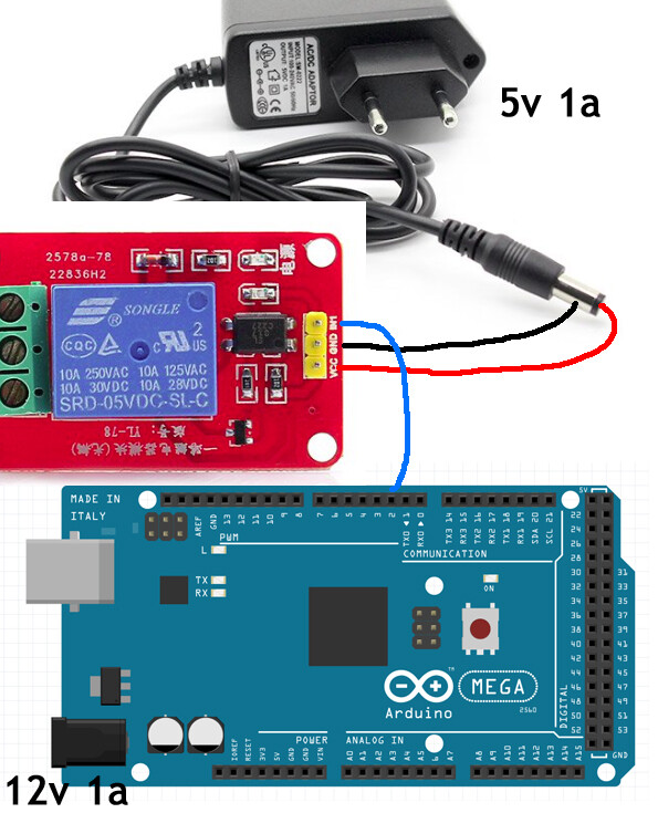
So I decide to connect all my relays (pin's + & -) to an external power supply (5v 2A) and only plug the "signal" pin of all the relays to my board. I did a test with one relays only and it doesnt work
The relays work fine, with the + & ground, plugged directly to the board...
In fact I'm going to plug many thing's on this "central" board like sensor (temperature, light, tilt, ir motion, analog distance) and ethernet, sd card, bluetooth module.
By example the analog light sensor work well with this "independant" power source but temperature and humidity dont too
How do you manage this problem ? Why created a board with so many pin ?
disconnect all the relays from your board. you will destroy your mega.
make a sketch and post what you have connected.
it should be power to the relay, relay to the transistor or FET, that device to ground.
you feed the transistor or FET a signal of some lower power from your device.
with a few relays, you can use transistors. with lots, you are better off with FETs as FETs do not use the power that the transistor does.
if you buy a relay board it might have opto isolators. those consume power as well.
to your question of why so many pins, there are two uses here. power and signals.
it has so many pins to talk to many devices. it does not have enough power to power very many devices.
you need to add a device that will talk to your board and power your devices. learn about FET's and even shift registers.
So I decide to connect all my relays (pin's + & -) to an external power supply (5v 2A) and only plug the "signal" pin of all the relays to my board. I did a test with one relays only and it doesnt work smiley-sad
The reason your test setup in that picture is not working is because you don't have a ground wire from the relay module to an arduino ground pin. One wire alone doesn't comprise a complete circuit for the arduino digital output pin.
So if I plug the ground wire from the module to the arduino its should work ?
And will it let me plug a lot of module like this one to the board without making it suffering ?
You should probably use opto-isolated relays. See THIS: part.
The MEGA is a very good design for automation, with lots of memory and I/O pins. But connecting to those pins can drive you crazy. You really need a Mega "Sensor Shield" that makes it easy to connect, with 3-pin connectors for every I/O. It also can use a separate power supply to feed the power pins. See THIS:
Here is an example of a Mega Sensor Shield on a Mega, with wires to terminal blocks for a bigger automation installation:
I got a mega sensor shield has recommended, but I think I burn the mega :o(
I put five volts to the sensor shield and twelve to arduino. I remove the jumper from the shield.
Is it ok like this ? because I suspect a bad manipulation from me... But I dont want to burn another mega.
I got a mega sensor shield has recommended, but I think I burn the mega :o(
I put five volts to the sensor shield and twelve to arduino. I remove the jumper from the shield.
Is it ok like this ? because I suspect a bad manipulation from me... But I dont want to burn another mega.
Thank's a lot
I would like to see a link to your specific mega sensor shield to be sure, but it does sound like you did it properly. Removing the jumper on sensor shield should 'isolate' the arduino board's 5V pin such that any sensors wired to the sensor board will draw 5 vdc current from your external +5vdc supply wired to the shield board. At least that is how my Uno type sensor shield works and I've confirmed that with an ohm meter.
What is happening here??? Let's try to figure this out.
Are both Mega's definitely dead? If you plug them with USB only to your computer can you upload BLINK? Does the PWR LED come on? Does the PIN13 LED blink at ALL?
If you have a Mega that will load BLINK from USB, can you disconnect it, plug on the Sensor Shield with NOTHING connected to it. Then plug USB back in. Does that work??
Need to divide and conquer this problem.
Where are you located? Maybe I can get another sensor shield to you..
Sorry for the problems; sometimes these things can be very frustratring.
Thank's for your help and your website
Yes both arduino's dont light anything when plugged alone on usb... And even windows dont recognize any com port.
They are definitly burnt ? My FTDI is comming soon if it could help ? But the power area on the arduino board was hot I think the two round "condensator" are dead
I'm in France, but I still have few more arduino's and I/O shield.
Finally I got it working. I changed the I/O shield, and place some tape on the new arduino usb port, it was touching the shield. And I'm seriously thinking wearing gloves when manipulating my setup.
Can you just confirm me that the config on my last picture is correct ???
Of course the 5V on the picture is plugged to the blue connector properly.
That looks right.. The Mega only "needs" 9V, but the 12V should be fine. In your configuration there is very little current coming from the onboard 5V regulator on the Mega.
I will look closely at the physical clearance between the Mega and the Mega Sensor Shield and put some warning on my sites.
Other Thing: You might try, just as experiment: If you apply 5V on a "dead" mega from GND-5V does it light up at all?
Il est temps pour une bonne chance avec votre projet!
Yes
I hesitate suggest you to add a picture like that to your website and may be adding a complete setup picture too (with the two DC adaptater) because it's not so intuitive for a newbe like me.
I will try to re-born this mega's with your method. If I understood well I could bypass the power socket... great
As you said I should have a better moment now 8) but it's the price of learning... I'll take care of this kind of short cut for a while now.
As Napoleon said.. A picture is better then 1000 words 8)
I still have a "leak" of power when I connect the sensor shield. Any idea from where it could come ?
Is it a short cut or a normal behaviour about missing something ?