Hello there...
I have a question and it is concerning a successive readings of analog inputs on MEGA.
To explain, I use all of 16 inputs on MEGA and on each input exists voltage divider (with two resistors) and 1nF capacitor between analog inputs and GND.
Here is a schema:
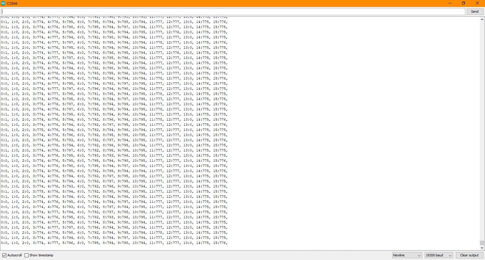
In this moment there is nothing connected to A0,A1,A2,A6 and A13 and readings should be zero.
But ONLY on A0 I get occasionally reading 1. I tried to start reading from A1 (to ignore A0). Then I get that "1" on A1...
In void get_analog you can see one line as comment. If I let that comment to be line of code ( except -----if inserted A0 works correctly) than reading of A0 is 0.
Why?
There can always be a variation in the least significant bit.
When reading multiple analog inputs, its advised to read each input twice and throw the first result away. That's what your xample with the additional line does (only for A0).
Your revised code should take care of the readings, giving the voltage more time to settle at the new level (i.e. charge the ADC sample and hold capacitor) after the prior reading.
I tested it already with double readings and without delay and I got all zeros where they should be...
I am not sure that I understand what CrossRoads ment with "give more time"....
When you read from a different analog input to your last analogRead call, part of the process of the reading is to switch the internal multiplexer to the new input. This means that the sample-and-hold capacitor in the ADC does not have sufficient time to stabilise if your analog source has an impedance greater than a few kΩ.
The solution is either to ensure the source is a low impedance, preferably no more than 1 kΩ, or to allow sufficient time for the sample-and-hold capacitor to stabilise. Since the call to analogRead does not allow enough time, calling it a second time, even if pretty much immediately, with the same input pin specified, gives it the necessary time as the multiplexer is already switched to that same input.
Yes.
It makes sense when for example my A0 is 0.5V and my A1 is 4.5V and I use source with impedance greater than 1k....So than sample-and-hold capacitor does not have enough time to "settle at right position".
But my A0 is 0V. I suppose that state of sample-and-hold capacitor before taking first conversion is empty ( or maybe not - left charged from last A15 sampling???? correct me here please )
Why ,if capacitor is empty, my reading of 0V is not 0?
To be honest...After the code was uploaded to MEGA i didnt look at very first result of ADC... I think that only in that case I can say sampling capacitor was empty...and maybe that reading was always 0...
So, I am not familiar so deep with ATMega2560 MCU... My question for you is what is happening with sampling capacitor after ADC is finished? is it discharged automatically or it is left in state as it was in the moment of sampling?
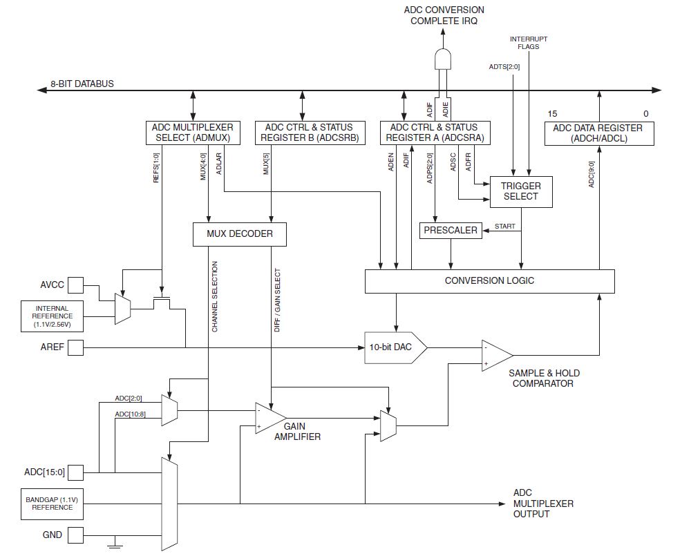
"The ADC contains a Sample and Hold circuit which ensures that the input voltage to the ADC is held at a constant level during conversion."
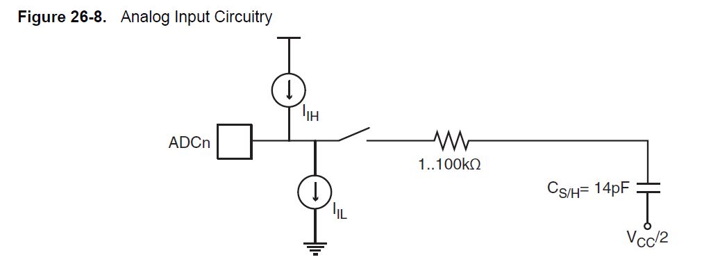
"The analog input circuitry for single ended channels is illustrated in Figure 26-8 on page 276 An analog source applied to ADCn is subjected to the pin capacitance and input leakage of that pin, regardless of whether that channel is selected as input for the ADC. When the channel is selected, the source must drive the S/H capacitor through the series resistance (combined resistance in the input path)."
"The ADC is optimized for analog signals with an output impedance of approximately 10kohm or less. If such a source is used, the sampling time will be negligible. If a source with higher impedance is used, the sampling time will depend on how long time the source needs to charge the S/H capacitor, which can vary widely. The user is recommended to only use low impedant sources with slowly varying signals, since this minimizes the required charge transfer to the S/H capacitor."