Hello everyone! I'm quite new to electronics and coding, but I decided creating custom MIDI controllers for an art instalation for a uni project would be a great way to teach myself. However, I am completely stuck after spending two days reading up on everything about it I could and looking at other people's code and tutorials. The idea it to use a bunch of cool sensors to control various aspects of the music that's playing and set all of it up as an instalation where people can come and have fun and create music with others.
I began by building a simple DIN MIDI output and tested it on the arduino and it works fine, it sent MIDI notes to my volca keys with no issue.
Then I decided to start small and add an LDR to control the cutoff. I tested a simple LDR circuit and it worked just fine. Then I tried adding the MIDI library to it and I just can't get it to work. I tried the same code with a regular 10k potentiometer and it kinda worked, I could adjust the cutoff, but multiple knobs were still lighting up meaning more than one MIDI CC is getting a MIDI message from the arduino.
I am using the Arduino Mega 2560 clone from Joy-it, and I've tested this code on two different synths. The serial print values make no sense what-so-ever too.
Anyway, here's the code:
// This sketch is a test of the MIDI Library by Francois Best
// Using an LDR to control the cutoff on the Volca Keys (MIDI CC 44)
// copyright Queer_Gabe 2023 ESML

#include <MIDI.h>

MIDI_CREATE_DEFAULT_INSTANCE();

int ldrPin = A0; // select the input pin for LDR

int ldrValue = 0; // variable to store the value coming from the sensor

void setup() {
Serial.begin(9600); //sets serial port for communication
pinMode(ldrPin, INPUT); // sets ldr as input
MIDI.begin(MIDI_CHANNEL_OMNI); // initialize MIDI library

}
void loop()
{
ldrValue = analogRead(ldrPin); // read the value from the sensor
ldrValue = ldrValue/7; // divide by 7 to make it fit better with MIDI values
ldrValue = constrain(ldrValue, 0, 127); // force it to be within MIDI values

MIDI.sendControlChange(44, ldrValue, 1); //send the MIDI CC message to channel 1

Serial.print("Cutoff");
Serial.println(ldrValue); //prints the values coming from the sensor

delay(100); // keep it from flooding the arduino with too many messages

}
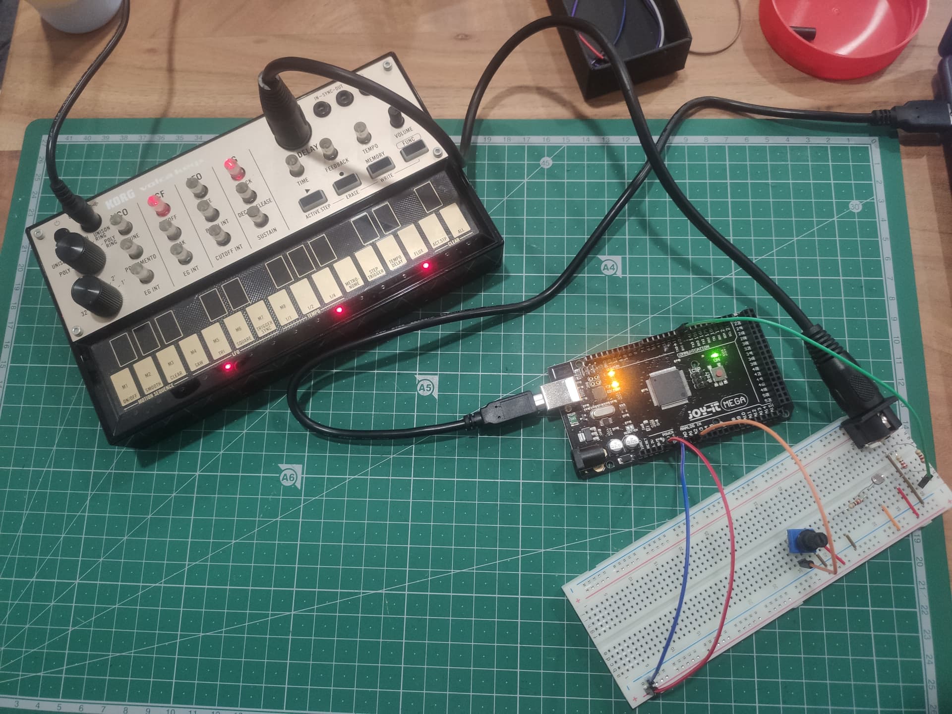
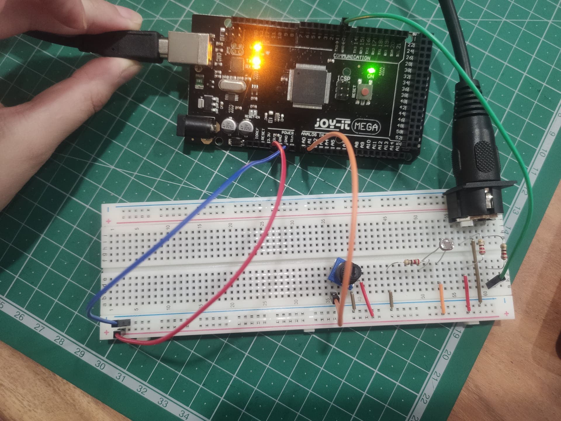
And here's a couple pictures of my breadboad, I have both the potentiometer and the ldr here and I just swap the orange cable to test one or the other.
I'm sure I'm missing something really basic, but I am still in that point where I don't even know enough to know what I don't know xD What is wrong with my code?
/*
  ASCII table

  Prints out byte values in all possible formats:
  - as raw binary values
  - as ASCII-encoded decimal, hex, octal, and binary values

  For more on ASCII, see http://www.asciitable.com and http://en.wikipedia.org/wiki/ASCII

  The circuit: No external hardware needed.

  created 2006
  by Nicholas Zambetti <http://www.zambetti.com>
  modified 9 Apr 2012
  by Tom Igoe

  This example code is in the public domain.

  https://www.arduino.cc/en/Tutorial/BuiltInExamples/ASCIITable
*/

void setup() {
  //Initialize serial and wait for port to open:
  Serial.begin(9600);
  while (!Serial) {
    ;  // wait for serial port to connect. Needed for native USB port only
  }

  // prints title with ending line break
  Serial.println("ASCII Table ~ Character Map");
}

// first visible ASCIIcharacter '!' is number 33:
int thisByte = 33;
// you can also write ASCII characters in single quotes.
// for example, '!' is the same as 33, so you could also use this:
// int thisByte = '!';

void loop() {
  // prints value unaltered, i.e. the raw binary version of the byte.
  // The Serial Monitor interprets all bytes as ASCII, so 33, the first number,
  // will show up as '!'
  Serial.write(thisByte);

  Serial.print(", dec: ");
  // prints value as string as an ASCII-encoded decimal (base 10).
  // Decimal is the default format for Serial.print() and Serial.println(),
  // so no modifier is needed:
  Serial.print(thisByte);
  // But you can declare the modifier for decimal if you want to.
  // this also works if you uncomment it:

  // Serial.print(thisByte, DEC);


  Serial.print(", hex: ");
  // prints value as string in hexadecimal (base 16):
  Serial.print(thisByte, HEX);

  Serial.print(", oct: ");
  // prints value as string in octal (base 8);
  Serial.print(thisByte, OCT);

  Serial.print(", bin: ");
  // prints value as string in binary (base 2) also prints ending line break:
  Serial.println(thisByte, BIN);

  // if printed last visible character '~' or 126, stop:
  if (thisByte == 126) {  // you could also use if (thisByte == '~') {
    // This loop loops forever and does nothing
    while (true) {
      continue;
    }
  }
  // go on to the next character
  thisByte++;
}
You may need to pick a different serial port for the MIDI
I just ran that sketch and it works as expected, so that doesn't seem to be the issue.
Good to know! I do believe it's an issue with my code or with my lack of understanding of how circuits work, or both!
to keep your Serial.printing from getting confused with the MIDI communication.
// This sketch is a test of the MIDI Library by Francois Best
// Using an LDR to control the cutoff on the Volca Keys (MIDI CC 44)
// copyright Queer_Gabe 2023 ESML

#include <MIDI.h>

MIDI_CREATE_INSTANCE(HardwareSerial, Serial1, MIDI);

int ldrPin = A0; // select the input pin for LDR

int ldrValue = 0; // variable to store the value coming from the sensor

void setup() {
Serial.begin(9600); //sets serial port for communication
pinMode(ldrPin, INPUT); // sets ldr as input
MIDI.begin(MIDI_CHANNEL_OMNI); // initialize MIDI library

}
void loop()
{
ldrValue = analogRead(ldrPin); // read the value from the sensor
ldrValue = ldrValue/7; // divide by 7 to make it fit better with MIDI values
ldrValue = constrain(ldrValue, 0, 127); // force it to be within MIDI values

MIDI.sendControlChange(44, ldrValue, 1); //send the MIDI CC message to channel 1

Serial.print("Cutoff");
Serial.println(ldrValue); //prints the values coming from the sensor

delay(100); // keep it from flooding the arduino with too many messages

}