Millis and multiplexing problem [CLOSED]

Hi! I am working on the following code. What I would like to do is to display the information at a certain time interval on classic 7 segment display, but without the delay() function, also, I am using two multiplexers 74hc595. I tried something with an if statement and millis(), but my display flickers and it doesn't work well at all. I also tried with while loops.
Who has time to help me?

void loop() {
  chk = DHT.read(DHT11_PIN);  //Read data of sensor DHT11
  temp = DHT.temperature; //Reading the Temperature
  umid = DHT.humidity; //Reading the Humidity
  unsigned long currentMillis = millis();

  if (currentMillis - previousMillis > 3000) { //Timer of 3 seconds
    previousMillis = currentMillis;

    if (State == LOW) {
      State = HIGH;
      unitTemp = temp % 10;
      perTemp = temp / 10;

      digitalWrite(latchPin, LOW);
      shiftOut(dataPin, clockPin, LSBFIRST, 2);                  //Set DISPLAY 1 (top view from left to right)
      shiftOut(dataPin, clockPin, LSBFIRST, num[perTemp]);   //Set the Temperature (ten)
      digitalWrite(latchPin, HIGH);

      digitalWrite(latchPin, LOW);
      shiftOut(dataPin, clockPin, LSBFIRST, 4);                  //Set DISPLAY 2
      shiftOut(dataPin, clockPin, LSBFIRST, num[unitTemp]);  //Set the Temperature (unit)
      digitalWrite(latchPin, HIGH);

      digitalWrite(latchPin, LOW);
      shiftOut(dataPin, clockPin, LSBFIRST, 8);                  //Set DISPLAY 3
      shiftOut(dataPin, clockPin, LSBFIRST, B11000110);         //Set the degree symbol [º]
      digitalWrite(latchPin, HIGH);

      digitalWrite(latchPin, LOW);
      shiftOut(dataPin, clockPin, LSBFIRST, 1);                  //Set DISPLAY 4
      shiftOut(dataPin, clockPin, LSBFIRST, B10011100);         //Set the symbol of Celsius [C]
      digitalWrite(latchPin, HIGH);

      digitalWrite(latchPin, LOW);
      shiftOut(dataPin, clockPin, LSBFIRST, 1);                   //Set DISPLAY 4
      shiftOut(dataPin, clockPin, LSBFIRST, ~255);                 //Reset the DISPLAY 4 (to avoid some flicking)
      digitalWrite(latchPin, HIGH);
    }
    else {
      State = LOW;
      unitUmid = umid % 10;
      perUmid = umid / 10;

      digitalWrite(latchPin, LOW);
      shiftOut(dataPin, clockPin, LSBFIRST, 2);                  //Set DISPLAY 1
      shiftOut(dataPin, clockPin, LSBFIRST, num[perUmid]);   //Set the Humidity (ten)
      digitalWrite(latchPin, HIGH);

      digitalWrite(latchPin, LOW);
      shiftOut(dataPin, clockPin, LSBFIRST, 4);                  //Set DISPLAY 2
      shiftOut(dataPin, clockPin, LSBFIRST, num[unitUmid]);  //Set the Humidity (unit)
      digitalWrite(latchPin, HIGH);

      digitalWrite(latchPin, LOW);
      shiftOut(dataPin, clockPin, LSBFIRST, 8);                  //Set DISPLAY 3
      shiftOut(dataPin, clockPin, LSBFIRST, B11000110);         //Set the upper symbol of percentage [%] of Humidity
      digitalWrite(latchPin, HIGH);

      digitalWrite(latchPin, LOW);
      shiftOut(dataPin, clockPin, LSBFIRST, 1);                  //Set DISPLAY 4
      shiftOut(dataPin, clockPin, LSBFIRST, B00111010);         //Set the lower symbol of percentage [%] of Humidity
      digitalWrite(latchPin, HIGH);

      digitalWrite(latchPin, LOW);
      shiftOut(dataPin, clockPin, LSBFIRST, 1);                  //Set Display 4
      shiftOut(dataPin, clockPin, LSBFIRST, ~255);                //Reset the DISPLAY 4 (to avoid some flicking)
      digitalWrite(latchPin, HIGH);
    }
  }

} // loop

This is still not a precise enough description of what your display does.

The basic code seems to be OK.
Your code does the bit-shifting only once every 3 seconds.

I don't remember exact how shift-registers of type 74hc595 work.
But I guess you should shift through all bits from bit zero up to bit 15 and toggle the latch only one single time if all bits are shifted to the place they shall be

best regards Stefan

I tried several things to get rid of delay() and replace it with millis(). I can see the display switching between temperature and humidity but it keeps flickering.

Do you understand what toggling latch only one single time means?
Yes you do

The code doesn't look like it will put numbers on the display in a satisfactory manner even without worrying that it not do for three seconds or seven or whatever.

You mixed the multiplexing up with the longer timing issue and it can't work quite that way.

Have you successfully just displayed a number, like 1234 however many digits, that sits there looking pretty?

Post that code, and we can help you make that happen for three seconds only.

a7

don't know if you realize you need to individually display each digit, giving each digit a chance to be seen and repeatedly cycling through each digit.

following works on a MultiFunction Shield. i believe the bytes are swapped from your HW

#define LatchPin   4
#define ClockPin   7
#define DataPin    8

const byte SegMap[] = {
    0xC0, 0xF9, 0xA4, 0xB0, 0x99, 0x92, 0x82, 0xF8, 0X80, 0X90
};

const byte Ndigit = 4;
byte digit [Ndigit] = { 1, 2, 4, 6 };
int  idx;

unsigned long msecLst;

// -----------------------------------------------------------------------------
void
disp7seg ()
{
    byte val = digit [idx];

    digitalWrite(LatchPin, LOW);
    shiftOut(DataPin, ClockPin, MSBFIRST, SegMap [val]);
    shiftOut(DataPin, ClockPin, MSBFIRST, 1 << idx);
    digitalWrite(LatchPin, HIGH);

    if (Ndigit <= ++idx)
        idx = 0;
}

void
dispVal (
    unsigned val )
{
    for (int n = Ndigit-1; n >= 0; n--)  {
        digit [n] = val % 10;
        val /= 10;
    }
}

void loop ()
{
    unsigned long msec = millis ();
    if (msec - msecLst >  5)  {
        msecLst = msec;

        dispVal (msec / 1000);
        disp7seg ();
    }
}

void setup ()
{
    Serial.begin (9600);

    pinMode (LatchPin, OUTPUT);
    pinMode (DataPin,  OUTPUT);
    pinMode (ClockPin, OUTPUT);
}
#include "dht11.h"       //Temperature and Humidity Library
dht11 DHT;               //Define the name DHT for the sensor of Temperature and Humidity
#define DHT11_PIN 8     //Sensor DHT11 conected to the pin 11 on Arduino
int chk;

int clockPin = 11; // Pin 8 of Arduino connected in the pin 11 of 74HC595 (Clock) SH_CP
int latchPin = 10; // Pin 9 of Arduino connected in the pin 12 of 74HC595 (Latch) ST_CP
int dataPin = 9; // Pin 10 of Arduino connected in the pin 14 of 74HC595 (Data)DS

int temp, umid;
int unitTemp, perTemp, unitUmid, perUmid;

byte num[] = {
  // A B C D E F G DP
  B11111100, // Zero
  B01100000, // One
  B11011010, // Two
  B11110010, // Three
  B01100110, // Four
  B10110110, // Five
  B10111110, // Six
  B11100000, // Seven
  B11111110, // Eight
  B11110110, // Nine
};

unsigned long previousMillis = 0;        // will store last time LED was updated
const long interval = 3000;           // interval at which to blink (milliseconds)
unsigned long ti;

void setup() {

  pinMode(latchPin, OUTPUT); // Define the 3 digital pins as output
  pinMode(clockPin, OUTPUT);
  pinMode(dataPin, OUTPUT);
  
}
void loop() {
  
  chk = DHT.read(DHT11_PIN);  //Read data of sensor DHT11
  temp = DHT.temperature; //Reading the Temperature
  umid = DHT.humidity; //Reading the Humidity
  ti = millis();
  
  while ((millis() - ti) < 3000) {
    unitTemp = temp % 10;
    perTemp = temp / 10;

    digitalWrite(latchPin, LOW);
    shiftOut(dataPin, clockPin, LSBFIRST, 2);                  //Set DISPLAY 1 (top view from left to right)
    shiftOut(dataPin, clockPin, LSBFIRST, num[perTemp]);   //Set the Temperature (ten)
    digitalWrite(latchPin, HIGH);

    digitalWrite(latchPin, LOW);
    shiftOut(dataPin, clockPin, LSBFIRST, 4);                  //Set DISPLAY 2
    shiftOut(dataPin, clockPin, LSBFIRST, num[unitTemp]);  //Set the Temperature (unit)
    digitalWrite(latchPin, HIGH);

    digitalWrite(latchPin, LOW);
    shiftOut(dataPin, clockPin, LSBFIRST, 8);                  //Set DISPLAY 3
    shiftOut(dataPin, clockPin, LSBFIRST, B11000110);         //Set the degree symbol [º]
    digitalWrite(latchPin, HIGH);

    digitalWrite(latchPin, LOW);
    shiftOut(dataPin, clockPin, LSBFIRST, 1);                  //Set DISPLAY 4
    shiftOut(dataPin, clockPin, LSBFIRST, B10011100);         //Set the symbol of Celsius [C]
    digitalWrite(latchPin, HIGH);

    digitalWrite(latchPin, LOW);
    shiftOut(dataPin, clockPin, LSBFIRST, 1);                   //Set DISPLAY 4
    shiftOut(dataPin, clockPin, LSBFIRST, ~255);                 //Reset the DISPLAY 4 (to avoid some flicking)
    digitalWrite(latchPin, HIGH);
  }
  delay(500);
  ti = millis();
  while ((millis() - ti) < 3000) { //Timer of 3 seconds for the Humidity
    unitUmid = umid % 10;
    perUmid = umid / 10;

    digitalWrite(latchPin, LOW);
    shiftOut(dataPin, clockPin, LSBFIRST, 2);                  //Set DISPLAY 1
    shiftOut(dataPin, clockPin, LSBFIRST, num[perUmid]);   //Set the Humidity (ten)
    digitalWrite(latchPin, HIGH);

    digitalWrite(latchPin, LOW);
    shiftOut(dataPin, clockPin, LSBFIRST, 4);                  //Set DISPLAY 2
    shiftOut(dataPin, clockPin, LSBFIRST, num[unitUmid]);  //Set the Humidity (unit)
    digitalWrite(latchPin, HIGH);

    digitalWrite(latchPin, LOW);
    shiftOut(dataPin, clockPin, LSBFIRST, 8);                  //Set DISPLAY 3
    shiftOut(dataPin, clockPin, LSBFIRST, B11000110);         //Set the upper symbol of percentage [%] of Humidity
    digitalWrite(latchPin, HIGH);

    digitalWrite(latchPin, LOW);
    shiftOut(dataPin, clockPin, LSBFIRST, 1);                  //Set DISPLAY 4
    shiftOut(dataPin, clockPin, LSBFIRST, B00111010);         //Set the lower symbol of percentage [%] of Humidity
    digitalWrite(latchPin, HIGH);

    digitalWrite(latchPin, LOW);
    shiftOut(dataPin, clockPin, LSBFIRST, 1);                  //Set Display 4
    shiftOut(dataPin, clockPin, LSBFIRST, ~255);                //Reset the DISPLAY 4 (to avoid some flicking)
    digitalWrite(latchPin, HIGH);
  }
  delay(500);
} // loop

Weird thing, it works fine with this code, but I want to get rid of the delay() function. What I came up with to do this affected the multiplexing.

Excuse me, I'm not the most skilled, this is how I saw it through several sketches, for each new display I should do this. From an Arduino tutorial:

for (int x = 0; x < n; x++) {

digitalWrite(latchPin, 0);

shiftOut(dataPin, clockPin, 255);

shiftOut(dataPin, clockPin, 255);

digitalWrite(latchPin, 1);

delay(d);

digitalWrite(latchPin, 0);

shiftOut(dataPin, clockPin, 0);

shiftOut(dataPin, clockPin, 0);

digitalWrite(latchPin, 1);

delay(d);

}

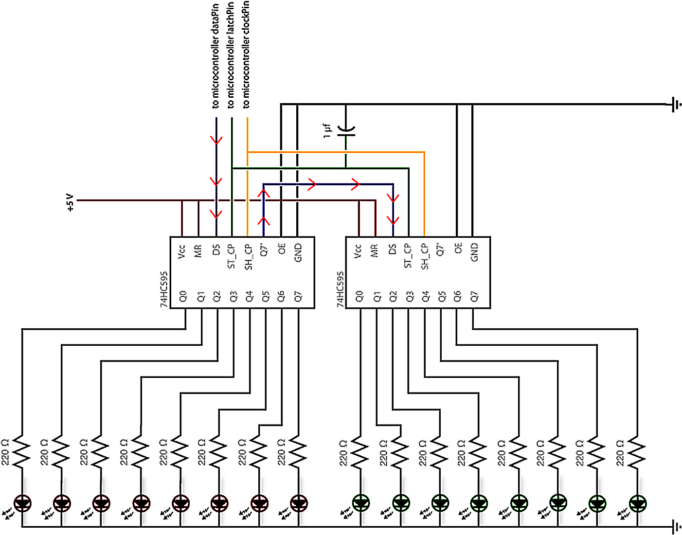
are your two shiftregisters daisy-chained?
which means they are connected like this?

Yes they are as can be see in the schematic of the first post

I have looked up some tutorials and most of them are doing it wrong!

As long as you have a single 74595 toggling the latch-input after 8 bit is correct.

As soon as you start daisy chaining 74595-bitshiftregisters giving a pulse on the latch pin is only done after ALL bits are shifted in

two 74595:__ single latch-pulse after 2 x 8 =16 bits
three 74595: single latch-pulse after 3 x 8 =24 bits
four 74595:_ single latch-pulse after 4 x 8 =32 bits
five 74595:__ single latch-pulse after 5 x 8 =40 bits

giving a pulse on the latch-input means the momentare bitpattern is stored into the storage register and the leds light up

                        8 bit |  8 bit | 8 bit
                      1st 595 | 2nd 595| 3rd 595
                      1       | 10     |   20
        Bit-position  12345678|90123456|78901234 
                      00000000|00000000|00000000   
                              |        |   
Bitpattern to display 01000111|11110000|00000001 
                              |        |   
after  1 clock-pulse          |        |   
                      10000000|00000000|00000000   
after  2 clock-pulses         |        |   
                      01000000|00000000|00000000   
after  2 clock-pulses         |        |   
                      00100000|00000000|00000000   
....
after  8 clock-pulses         |        |   
                      00000001|00000000|00000000   
after  9 clock-pulses         |        |   
                      00000000|10000000|00000000   
after 10 clock-pulses         |        |   
                      00000000|01000000|00000000   
after 11 clock-pulses         |        |   
                      00000000|00100000|00000000   
after 12 clock-pulses         |        |   
                      00000000|00010000|00000000   
after 13 clock-pulses         |        |   
                      10000000|00001000|00000000   


if you give a latch-pulse after 16 bits the display shows
                      11110000|00000001|00000000   
instead of            01000111|11110000|00000001

because the bits are not YET at the correct position
.
.
only if you give a S I N G L E latch-pulse after 24 bits
the shifted pattern   01000111|11110000|00000001   
matches exactly       01000111|11110000|00000001

that is the reason why the latch-pulse is given only ONCE after ALL bits are shifted to their correct position.

here is a tutorial that explains the details

best regards Stefan

The schematic in post #1 shows they are. Do you suspect @cristian10001 has not followed the schematic correctly?

This comment seems to indicate the display does work with the code in post #7, and I don't think it would work at all if the registers were not chained.

Why do you want to get rid of the delay() function?

Using delay() is not a problem unless you need your code to perform other "tasks" such as monitoring buttons at the same time as multiplexing the display. Even in some of those cases, you can still use delay() provided they are only short ones (<100ms).

So before we begin the effort of removing the delay(), please explain why you want to do that.

Your point is correct, so with that delay (500) between displays it works very well. My intention is to get rid of delay() and use millis(). The ICs are chained, and I even made a homemade pcb (this is not the problem after all). I have other such circuits made and they work well.
I didn't think that a sketch like this would complicate things.

Can anyone explain why it works with the delay and flickers without?

I mess up with the timings.
This code works almost correctly:

void loop() {

  chk = DHT.read(DHT11_PIN);  //Read data of sensor DHT11
  temp = DHT.temperature; //Reading the Temperature
  umid = DHT.humidity; //Reading the Humidity
  //ti = millis();
  unsigned long currentMillis = millis();

  if (currentMillis - previousMillis >= 6000) {
    currentMillis = previousMillis;
    ti = millis();
    while ((millis() - ti) < 3000) {
      unitTemp = temp % 10;
      perTemp = temp / 10;

      digitalWrite(latchPin, LOW);
      shiftOut(dataPin, clockPin, LSBFIRST, 2);                  //Set DISPLAY 1 (top view from left to right)
      shiftOut(dataPin, clockPin, LSBFIRST, num[perTemp]);   //Set the Temperature (ten)
      digitalWrite(latchPin, HIGH);

      digitalWrite(latchPin, LOW);
      shiftOut(dataPin, clockPin, LSBFIRST, 4);                  //Set DISPLAY 2
      shiftOut(dataPin, clockPin, LSBFIRST, num[unitTemp]);  //Set the Temperature (unit)
      digitalWrite(latchPin, HIGH);

      digitalWrite(latchPin, LOW);
      shiftOut(dataPin, clockPin, LSBFIRST, 8);                  //Set DISPLAY 3
      shiftOut(dataPin, clockPin, LSBFIRST, B11000110);         //Set the degree symbol [ยบ]
      digitalWrite(latchPin, HIGH);

      digitalWrite(latchPin, LOW);
      shiftOut(dataPin, clockPin, LSBFIRST, 1);                  //Set DISPLAY 4
      shiftOut(dataPin, clockPin, LSBFIRST, B10011100);         //Set the symbol of Celsius [C]
      digitalWrite(latchPin, HIGH);

      digitalWrite(latchPin, LOW);
      shiftOut(dataPin, clockPin, LSBFIRST, 1);                   //Set DISPLAY 4
      shiftOut(dataPin, clockPin, LSBFIRST, ~255);                 //Reset the DISPLAY 4 (to avoid some flicking)
      digitalWrite(latchPin, HIGH);
    }
    // ***************************************************************************************************
    //delay(500);
    //ti = millis();
    while ( (((millis() - ti) > 3000)) && ((millis() - ti) < 6000) ) { //Timer of 3 seconds for the Humidity
      unitUmid = umid % 10;
      perUmid = umid / 10;

      digitalWrite(latchPin, LOW);
      shiftOut(dataPin, clockPin, LSBFIRST, 2);                  //Set DISPLAY 1
      shiftOut(dataPin, clockPin, LSBFIRST, num[perUmid]);   //Set the Humidity (ten)
      digitalWrite(latchPin, HIGH);

      digitalWrite(latchPin, LOW);
      shiftOut(dataPin, clockPin, LSBFIRST, 4);                  //Set DISPLAY 2
      shiftOut(dataPin, clockPin, LSBFIRST, num[unitUmid]);  //Set the Humidity (unit)
      digitalWrite(latchPin, HIGH);

      digitalWrite(latchPin, LOW);
      shiftOut(dataPin, clockPin, LSBFIRST, 8);                  //Set DISPLAY 3
      shiftOut(dataPin, clockPin, LSBFIRST, B11000110);         //Set the upper symbol of percentage [%] of Humidity
      digitalWrite(latchPin, HIGH);

      digitalWrite(latchPin, LOW);
      shiftOut(dataPin, clockPin, LSBFIRST, 1);                  //Set DISPLAY 4
      shiftOut(dataPin, clockPin, LSBFIRST, B00111010);         //Set the lower symbol of percentage [%] of Humidity
      digitalWrite(latchPin, HIGH);

      digitalWrite(latchPin, LOW);
      shiftOut(dataPin, clockPin, LSBFIRST, 1);                  //Set Display 4
      shiftOut(dataPin, clockPin, LSBFIRST, ~255);                //Reset the DISPLAY 4 (to avoid some flicking)
      digitalWrite(latchPin, HIGH);
    }
  }
  //delay(500);
} // loop

I have to make the timing perfect, sometimes there is a little flicker, but at least it switches from temp to humid.

If you want a really clean looking multiplexed display you need to use delays but they should occur after you display each digit. Put delay(10) after each time you bring the latch HIGH.

You don't need to reset digit 4, it just makes things worse.

This means if flickering occurs there must be someting wrong:

  • with the power-supply,
  • the on/off-switching of the transistors
  • or too many inbetween latch-pulses

after taking another close look to your schematic
I see the four digits are switched on/off with a transistor.
This means the you have to switch the transistors on/off in sync with the bits that shall light up for the digit.

This on/off-switching-frequency must be higher than 25 Hz better 50 or 60 Hz so the human eye can't distinguish anymore between on/off

This is the reason why I was asking in my very first post

Or to be more clear: how does the flickering look like?
once every 3 seconds?
2 times per second?
10 times per second?
etc. etc.

Reading in the dht-sensor needs some time. I do not know the time but I guess it will be more than 10 milliseconds and then the reading in of the dht-sensor reduces the speed of the loop.
And as you are indeed multiplexing with the transistors switching the transistors only with a frequency of 10 Hz or slower MUST result in flickering.
This can be solved by using a timer-interrupt in combination with a digit-buffer
For updating the digits your code writes into the digitbuffer

and the timer-interrupt that is running at a frequency of 100 Hz does nothing else but shiftout all bits all the time. Not only once every 3 seconds.

best regards Stefan

The code in #7.

When that code runs, what is showing on the display during the delay(500) calls between the while statements?

Most of the code should be reusable in restructuring the code just a bit, and taking a few of the suggestions on offer already.

If my late evening reading of the code isn't all wrong @jim-p suggestion to hang out a bit after each digit (delay()) is what I'd try first.

Right there in the post #7 code. 10 ms is a bit too long and implies a 25 Hz refresh rate, this will not need old people to see that it is happening.

Since the while loop is probably taking no significant computing time relative to milliseconds, you can use much shorter dwell times and achieve much higher refresh rates resulting in a rock solid bright non-flickering disalpy.

Play with it. Use 10 ms first, delay(10). Then for fun try 100. Then for real try 1 or 2.

And tell us what you observe.

TIA

a7

But your reason for that is top secret.

Something is still wrong, but I keep trying.