I would like to be able to record events and attach a timestamp with millisecond precision. My idea is to use a combination of an RTC such as DS3231 and an internal timer/counter in Arduino. Here is a general idea how it would work: RTC generates a signal every 1 second, and I don't mean just 1 Hz frequency signal, but a signal when a new second starts according to real time (at 000 milliseconds, not somewhere inside a second). This signal generates an external interrupt for Arduino which starts a timer which counts up to 1000 milliseconds. So when an event happens, for example a push on a button, the counted time is retrieved from the timer register (for example 326 milliseconds), the actual time is retrieved from RTC via I2C, and finally these two are combined to get the precise time.
I notice that DS3231 can generate a 1 Hz square wave on its pin INT/SQW. My question is this: Is this signal synchronized so that each rising/falling edge happens exactly at 000 milliseconds, i.e. when one second ends and another begins? If not, are there any other (better, simpler) ideas how to achieve my goal?
If you want to know when each second begins then I suggest a GPS receiver. Some of them, perhaps all of them, have a 1 pulse per second output that is aligned with the start of each second as per international references. You won't do better.
A simpler idea is to use the DS3231 to determine how fast or slow the Arduino clock is, then use millis() to time events, and rescale the results by the correction factor.
You do need to be aware that millis() occasionally it is off by 1 increment, since it counts to 1000 while the Arduino counts 1024 ticks of the CPU clock.
I would probably go for a free running timer with input capture.
In the capture interrupt you need to copy the capture register for later use.
After 2 captures you can calculate a correction factor.
The falling edge of the ~INT/SQW pin marks the time that the DS3231 will start replying with the new second. You could save the millis() (or micros()) that this pin falls, and use that timestamp as the reference from which to measure sub-second events.
One can also set the SQW to emit other than 1-Hz square waves.
Thanks for all the replies. There is some good advice there. Some of it addresses the issue of counting milliseconds which I don't see as a problem, at least for now.
Anyway, I saw the suggested video and also read some parts of the RTC datasheet. It seems to me that the 1 Hz square wave is not synchronized with the start of each second, but it just starts working as soon as the chip is energized. The other option, which might be promising, is to activate the SQW output when a value in the alarm register is matched, and one of those possible values is to generate an alarm every second. I can only suppose that this alarm is generated at the turn of the next second, but it is not explicit.
As for the GPS module, Neo-6M seems by far the most popular. But it doesn't have a digital pin, just serial communication. How do I get from it the exact instant of the start of new second? I suppose, if the module sends the new time to the Arduino immediately after the turn of the second, and if the transmission takes less than 1 ms, I could use the moment of reception of the new time as a trigger to start the internal timer. But is it so? Any other GPS module to recommend?
It's synchronized with the last write of the seconds register. It goes high at 500ms, and falls low at 1000ms. If you didn't take care in setting the seconds of the RTC at a millisecond-precise time, it holds that same offset to the best of its ability.
If you're referring to the imprecision of the Arduino clock: it is possible to use an external quartz oscillator. With it I am confident that I can get 1000 ms. I am using the timer function, not millis(). When the event happens I can read the value in the counter register, and since I know the oscillator frequency and the prescaler, I can calculate the time. Remember, the counter is reset every second. How much error can it accumulate in one second?
Ok, so if I get a 4 MHz oscillator, set the prescaler to 64, then 1 second equals 62500. Maximum value is 65535 for Timer1. 1 ms equals 62.5. All I need is to check the value in TCNT1 and divide by 62.5. Or am I getting something wrong? I can accept if due to rounding I get +/- 1 ms uncertainty.
Just brainstorming
Store the difference between millis() and zero in an int on the flank of the 1Hz RTC pulse.
The millis timestamp is "millis() + difference".
But that's still loads better than a stock Arduino's +/-0.5% ceramic oscillator
1000*3600*0.005=18000ms or +/-1000*0.005=5ms/sec
Along with saving the millis() I'd also increment a counter by 1000 each DS3231 falling edge and use the difference to measure the longer term accuracy and ratio so you'd know where on the +/-5ms/sec you'd expect to be. And I'd probably do it with micros() instead of millis() to avoid the 24 double-jumps in each second's worth of millis() incrementing.
Over how long of an interval is the millisecond precision needed?
Another thing to check is which board you are using. The Arduinos with built-in USB, like the Micro, use a much more accurate crystal than the cheap ceramic resonators in the Uno, Nano and Mega.
Brief explanation of what I am trying to do: I want to build a very simple version of a numerical protection relay. In the real world those devices are used for protection of power systems and machines such as generators, transformers, power lines, industrial plants etc. They need very precise and universal time reference so that later, when analyzing faults, the recordings from several relays located at a vast distance can be compared. As far as I know their time is synchronized at regular intervals with an outside source, probably GPS.
In reality I am going to build only one such device with Arduino Nano, and it will be infinitely less powerful and much simpler. And its recordings won't be compared to other devices, so in theory any time reference could be good enough. But I was still hoping to make it "as good as possible", ideally as precise as UTC. So if I am using a DS3231, it would probably help to synchronize its time as often as possible. As for the sub-second precision, some of you have suggested methods by which the controller basically measures its inaccuracy over time and "self corrects", and I might try that.
One other question now comes to mind: when calibrating time on DS3231, is it at all possible to synchronize it to UTC down to 1 ms? If not, then maybe I should move on to different ideas, or simply accept less accurate solutions.
Mine is a GlobalTop-FGPMMOPA6H, but I bought it ages ago so I imagine there are better ones available now.
I did a search on Amazon and found this:
I'm sure there are others.
On the one I have the serial data output is not reliably aligned to the start of a second, so cannot be used as a reference for the start of a second. I can't comment on whether that applies to other modules.
From the datasheet, Neo-6M has an output called TIMEPULSE (pin 3) :
1.7.2 Timepulse and frequency reference (page 8/25)
NEO-6T comes with a timepulse output which can be configured from 0.25 Hz up to 10 MHz. The timepulse can either be used for time synchronization (i.e. 1 pulse per second) or as a reference frequency in the MHz range.
From what I can see from table 1 page 5/28, not only the NEO-6T but all of them, including the NEO-6M, have that feature, at least up to 1kHz.
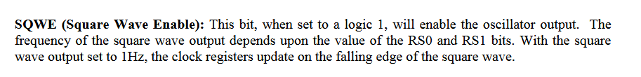
I find this description in the DS3231 data sheet rather confusing because it appears to mix (a) user instructions for setting the registers with (b) the normal behaviour of the INT/SQW pin.
It is not clear if the 500ms high transition referred to is a special case following a time update by the user or a regular activity by the device on each second rollover.
In any case the data sheet for the earlier DS1307, which is mainly register compatible with the DS3231, is much clearer:
I think it is describing the behavior of the square wave relative to the synchronization action of writing to the seconds register. If you want to synchronize the DS3231 to a GPS pulse, you'd write to the seconds register at the time of the GPS pulse.
It then resets its countdown chain, and when it ticks to down to 500ms, it writes HIGH to the SQW pin and when it get down to zero it writes LOW and updates its internal registers.
The normal operation of the SQW pin is to be in phase with the countdown chain with its falling edge at the end of the countdown and the rising edge a half period later. It isn't a free-running oscillator separate from the countdown chain.
As to:
Yes, the falling edge the falling edge is at 0 milliseconds and the rising edge is 1/2 period later.
If you're not counting a millisecond timepulse from a GPS, the sychronization tricks in here are worthwhile:
The "Advanced bresenham timing techniques" section might be most relevant to maintaining a millisecond precise register in sync with a timebase. The trick is to phase-lock a higher frequency counter to the signal that you do have, and use that to generate the signal that you want.
If you are using a GPS, or are looking at measuring industrial power, then this other page may be of interest: