I've got this fox ear headband that moves with sound. I'd like to get rid of the electret mic and use my Arduino to generate a signal in place of it. The existing DC motor controller is compact and fits nicely in the battery housing so I'd rather use it than a motor shield.
My plan: Cut off the mic and use the arduino to generate a tiny analog signal (maybe 10-100mv) to mimic the output of the electret. After searching the forums a bit I feel like I may need a voltage divider to get a signal this small (and I'm guessing anything bigger would overload the preamp circuit on the existing board).
Questions:
Will a PWM work in place of an analog signal?
I don’t know the exact specs for this mic and recognize the following assumptions might fry the pre-amp. To find the resistor needed to cut the voltage down I would do use the following: I need to drop 5v output from the arduino to .10V (output of the mic). 4.9v/.005A= 980Ohm
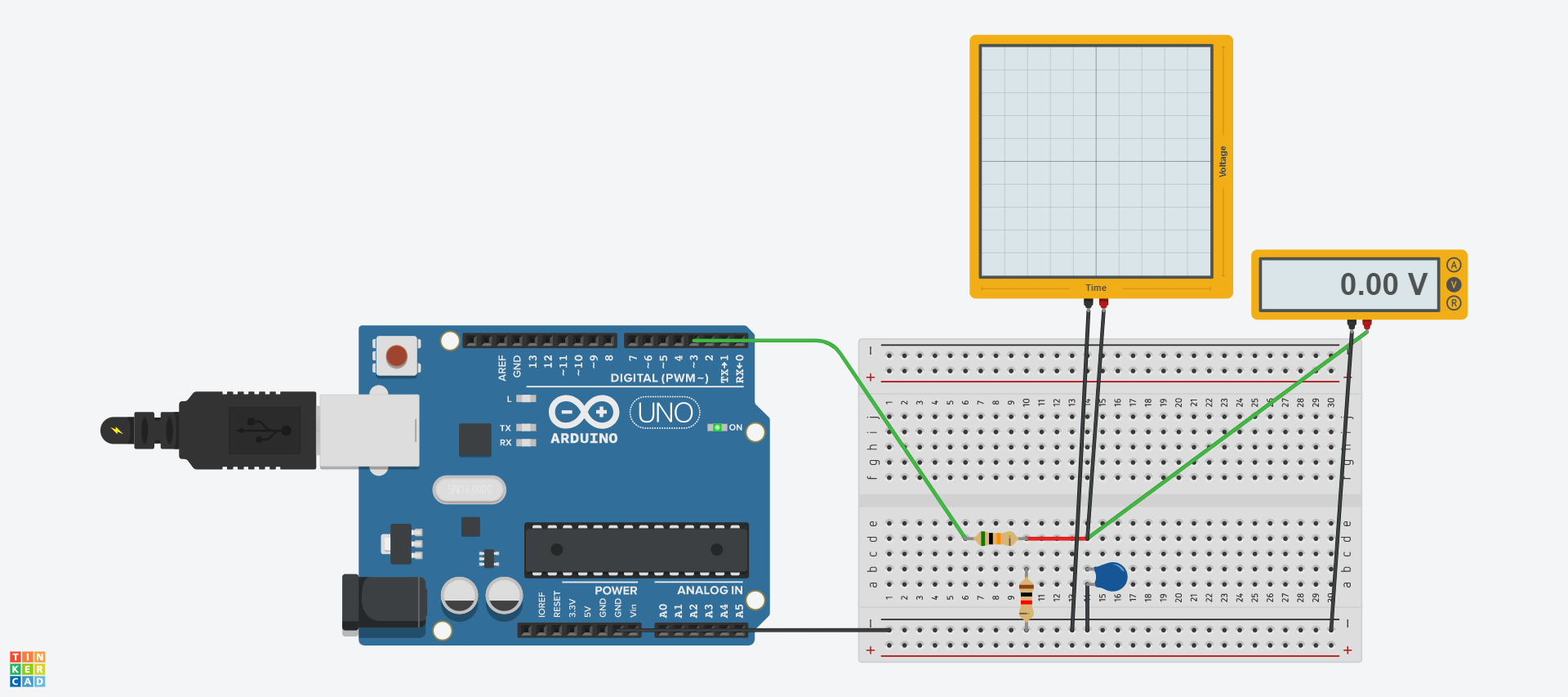
I just built this on Tinkercad and was using the o-scope to understand how low-pass filters work. Here's a photo and the link to my circuit.
You mentioned:
You may need a 10 uF series capacitor after C1 to block the DC.
How will I know if I need to do this? Is there a way to measure it? I don't think the Tinkercad scope is capable of 'zooming in' on the wave to examine it closely enough.
You also need to increase the frequency of the PWM to something like 40KHz, or above to simulate the audio signal from it.
Call a function like this in the setup function:-
void setPWMtimer(){
// Set timer1 for 8-bit fast PWM output to use as our analogue output
 TCCR1B = _BV(CS10); // Set pre scaler to full 16MHz
 TCCR1A |= _BV(COM1A1); // Pin low when TCNT1=OCR1A
 TCCR1A |= _BV(WGM10); // Use 8-bit fast PWM mode
 TCCR1B |= _BV(WGM12);
 OCR1AL = 0x80; // start PWM going at half maximum
}
That code in Post#3 will not produce anything remotely like an audio signal that is audible, it will be way way too slow. In fact it works out to be a triangle wave of 0.39 Hz, or a period of 2.56 seconds.
If your fox ear headband (about which I know nothing) requires it. Open up the headband and look carefully at the PCB to see if an input capacitor is present.
An electret microphone always has a bias voltage. The mike element varies the bias voltage output, so it never goes to zero and never goes above the bias voltage.
So, measure the mikes bias voltage if you are going to direct connect and replace the mike element. A capacitor is normally used to eliminate the bias voltage and produce an AC voltage for normal audio amplification.
@Paul_KD7HB Thanks for explaining that. I'm getting 3v into the electret mic and 0-2.5mV out of it with sound applied. One thing that's a bit confusing is that the output wire of the mic is going to the same pad on the circuit board as the motor. The motor's other pin gets a constant 2.5V so I'm thinking the reasoning behind this is that the mic's output affects the speed of the motor by
altering its path to ground somehow. Does that sound right?
Then there is not JUST an electric mike there. There is some electronic circuit. Otherwise you would get 1.5 volt out modulated + and - by the mike.
Sorry, there is nothing else to be done without a schematic of your device.