Hi!
I bought the IoT Oplà kit (MKR1010 and IoT Carrier) for my project.
I need to connect an external temperature sensor. I've bought a type K Thermocouple with a MAX6675 chip, using SPI.
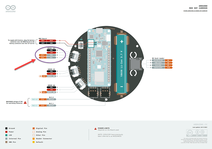
The problem is that the only "digital" input that seems to be free on carrier is the I2C and I don't know if I can use the connector of the I2C and change the pinout config to a SPI...
My other option is to find an RTD and use the analog input, but I'll need to find another "pre built circuit" to have a good precision on the RTD.
What do you think?
Thanks!
If I've got it I2C uses 2 pins but SPI uses 3 pins. SPI is for high speed communication and I2C is the "little brother".
Pleas post links to the datasheets of "an external temperature sensor".
As requested:
DataSheet of the MAX6675
https://cdn-shop.adafruit.com/datasheets/MAX6675.pdf
Tuto arduino with MAX6675
https://microcontrollerslab.com/max6675-thermocouple-arduino-tutorial/
Thanks!
Drop all thinking about I2C.
Reading the datasheet I find an SPI interface. If You only read one SPI device You can tie the CS to GND and read it using SClock and So (serial out). That could save on pin.
I don't know the MKR1010 board, what microcontroller it uses. I'm an Arduino UNO guy.... On those boards (with that controller) several of the analog pins can be used as digital!
If You post schematics the over all picture would be a lot more clear for helpers.
Hi tag_1911,
I'm having a close issue to yours and despite not having a direct answer for you will share my thoughts in the spirit of community sharing.
A) Same setup as yours: MKR IOT Carrier and Arduino MKR Wifi1010
B) Need to use the 11 SDA and 12 SCL pins
In my case, I wanted to use the pins mounted ON the Arduino MKR wifi1010 as I2C pins in order to receive data from another Arduino MKR wifi1010
Reading the documentation here below:
and having done a lot of tests with and without the carrier, I came to the conclusion (still to be validated) that if I mount Arduino MKR Wifi1010 to the MKR Iot Carrier then the 11 SCL and 12 SDA pins mounted ON the carrier become unavailable. In my case no I2C communication can take place.
So what?
My current ongoing trial is to source a "Grove - 4 pin Male Jumper to Grove 4 pin Conversion Cable"

and see if I will get access to the 11 SCL and 12 SDA pins back using the jumpers coming out from the Grove plug.
Not sure if this approach could be useful for you as well, just wanted to share my angle in the search for available pins when it comes to MKR IOT Carrier and Arduino MKR Wifi1010.
BR
Andrea
Another approach I found quite interesting and ingenious is here below:
Hi Andrea
I think, in your case, your approach will be OK.
Maybe it will too, with my case, but I'll have to use the other GROVE with the analog pin to get my CS signal.
I'll try to buy the same cable as you.
The other solution (with the monting kit) is not possible (and quite not pretty) for my setup.
This topic was automatically closed 180 days after the last reply. New replies are no longer allowed.
