At what point do I need to consider ventilation for my module box or even using heat sinks or a fan.
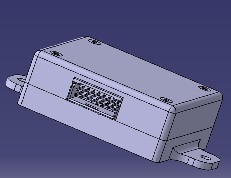
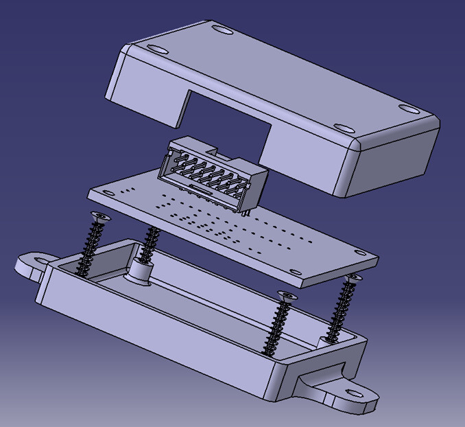
The pictures below show a proposed box I plan to make to house a project I am working on to drive a radiator fan for my car. The box is pretty well sealed with the exception of areas around the connectors. Details of the circuitry are presented in the picture below and the attached link.
The box dimensions are ~ 2.5" x 2.5" x 1". I have multiple modules in my car that are about that size and have lots of electronics in them and have no fans or even heat sinks mounted to the controller. But on the other hand if I take apart my engine management controller there are plenty of heat sinks and a fan does go into the computer box that holds the modules.
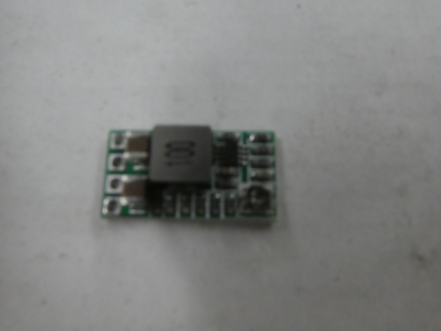
The first picture shows the proposed PCB board that will be going into the box. The second pictures shows a small DC to DC converter that will also go into the box. That converter has no real means of mounting it so I was hoping to just glue it down. But I don't know if that part gets hot and if glue would effect it in any way.
The third and fourth boxes show the the proposed module box.
And the last like will give more detail on how the PCB board was designed.
Regarding cooling of the electronics in the box You need to calculate and sum up all power losses inside the box.
Plastic boxes are rather isolating, not radiating out energy, temperature. Cooling fans suck in dust so every power dissipating circuit could use a heatsink mounted in a hole in the box raditing heat outside..
Do i miss the point?
Not at all. I get that but anything more than a resistor I don't know how to calculate the heat being dissipated. How much heat come out of the buck converter? or the caps and the nano.?
The one thing I will be able to do is monitor it with a TC and data logger.
Same formula. P = IV I is the current through the circuit (doesn't matter if its a resistor or a complex IC) and V is the voltage across the circuit.
So a typical Arduino Nano like board probably uses something like 50mA at 5V, or 250mW. Your switching regulator module is ... hard to predict. You can do the box as a whole: 13.8V (auto voltage) at 30mA going through a black box that is the arduino plus your circuit plus the voltage regulator would be about half a watt. (that assumes a reasonable efficiency for the regulator...)
A half watt probably isn't anything to worry about. IIRC, most of the interior lighting is ~5W, and they don't get hot enough to melt the plastic housings.
I get that but I have no idea how to calculate the current through the caps. In fact that whole circuit has been tested without caps and works fine that way on the bench. I'm assuming the current through the caps is negligible.
That's what I'm assuming is checking the box as a whole. I know ~20ma @ 13.8V comes in from the fan so that is about 280mW. And I can add what goes into powering up the Arduino, which I still need to measure. I will have the opportunity to measure that. So if it measures out at 250mW before the buck converter, then the total heat load in the box will be about 530mW.
The interior lights are an excellent analogy. Mercedes had some 10W courtesy lights that they needed to down grade to 5W because they were melting the plastic. They also had some 1.2W bulbs that were fit snugly into ABS plastic sockets that would melt when people tried to use a 2.4W bulb in its place, but in that case the bulb was actually surrounded by the ABS. So I guess in my case. 10 or so components with a total power of 1.2W spread out in a 4 in^3 box should be a piece of cake.
That little buck converter, I still need to find a way to mount. It has no mounting holes, so I would like to just epoxy it in place to the top of the case cover. Is it OK to put epoxy on the back of that circuit board?