Hello,
I've been tinkering with an accelerometer (http://www.robotsimple.com/MMA7341L_3_Axis_Accelerometer_3_11g?keyword=MMA7341L) with an Arduino Uno and was hoping I could get some answers to a few questions.
I've adapted one of the tutorials found here to add a Z axis and tweaked it a little.
/*
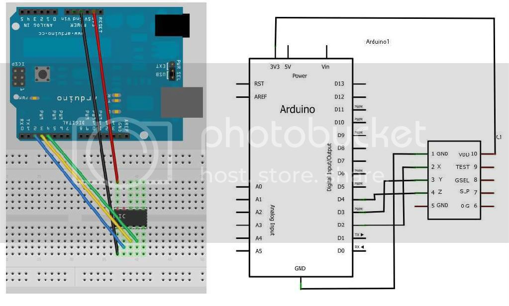
The circuit:
* X output of accelerometer to digital pin 2
* Y output of accelerometer to digital pin 3
* Z output of accelerometer to digital pin 4
* +V of accelerometer to +3.3V pin
* GND of accelerometer to ground
Adapted slightly from this tutorial
http://www.arduino.cc/en/Tutorial/Memsic2125
*/
// these constants won't change:
const int xPin = 2; // X output of the accelerometer
const int yPin = 3; // Y output of the accelerometer
const int zPin = 4;
void setup() {
// initialize serial communications:
Serial.begin(9600);
// initialize the pins connected to the accelerometer
// as inputs:
pinMode(xPin, INPUT);
pinMode(yPin, INPUT);
pinMode(zPin, INPUT);
}
void loop() {
// variables to read the pulse widths:
int pulseX, pulseY, pulseZ;
// variables to contain the resulting accelerations
int accelerationX, accelerationY, accelerationZ;
// read pulse from x- and y-axes:
pulseX = pulseIn(xPin,HIGH);
pulseY = pulseIn(yPin,HIGH);
pulseZ = pulseIn(zPin,HIGH);
// convert the pulse width into acceleration
// accelerationX and accelerationY are in milli-g's:
// earth's gravity is 1000 milli-g's, or 1g.
accelerationX = (((pulseX / 10) -500) * 8)-716; //I added the last value (-716) to try and calibrate the milli-g reading to 0
accelerationY = (((pulseY / 10) - 500) * 8)-720; //I added the last value (-720) to try and calibrate the milli-g reading to 0
accelerationZ = (((pulseZ / 10) - 500) * 8)-712; //I added the last value (-712) to try and calibrate the milli-g reading to 0
// print the acceleration
Serial.print(accelerationX);
// print a tab character:
Serial.print("\t");
Serial.print(accelerationY);
Serial.print("\t");
Serial.print(accelerationZ);
Serial.println();
delay(100);
}
Everything is “working” but I don't quite understand the numbers. When it's just sitting at rest the readings from the serial port are hovering around 0, but whenever I reach to touch the Arduino, the numbers jump to around -300 without my actually touching the Arduino. I'm still a novice with this thing, but recently when doing a tutorial on buttons I learned that buttons had to be debounced. Is that same thing happening here? If so, I could use some guidance on that, I can't find many tutorials on accelerometers.
For a project I'm working on (more about it below if you're interested) I would like the accelerometer readings to be a little more predictable. Right now I can set the arduino down in place or one certain position (propped up against a wall or on a book etc...) and the readings are never quite the same two times in a row. Is the accelerometer taking too fine of readings? And if that's the case is there a way to calibrate it so it takes more coarse readings?
Like I said, I'm a novice with these things. I'm primarily a geocacher with a lot of ambition and ideas, and not a whole lot of electronics skill. (Just enough to get myself in trouble, but I'm learning!) Here's what I want to happen eventually: I want a cube with an on/off switch and an LED that lights either green or red and a buzzer and a servo. The finder of my geocache turns the box on with a toggle switch and the LED lights red (indicating that they need to turn it to the correct side). The finder then rotates the box so a certain side of the box is up (each side has a different color, the finder will first have to solve an online puzzle that will give them the correct procedure/hints on how to open the box), and then they tap a predetermined number of knocks on that side, (ie. blue side 5 knocks, red side 3 knocks etc..) and if they knock the right number of times on the correct side the LED flashes green, if not red. Then the finder rotates the box again to the next correct side and taps again. After 4 or so times of the finder turning and tapping in the right order etc... the box chimes a nice DING and a servo moves a bar and allows the box to spring open. If during the procedure the finder gets something wrong the box sounds off with a negative sound and flashes the LED red. I have all the parts and I'm assembling them now, but the learning of the code is holding me back.
Any help or advice is greatly appreciated.
Cheers, DJ