Motor Project Not Working


Hi,

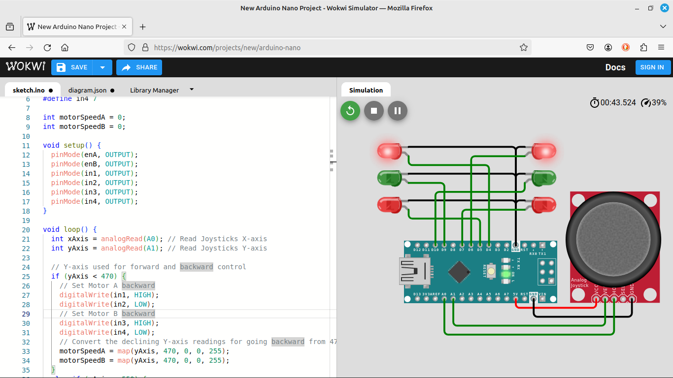
I am doing an Arduino Motor Project, however I unfortunately have got an issue with the movement of the DC Motors. The system uses a 2x DC Motors, Arduino Uno, H-Bridge and a Joystick. Currently the movement and action are as so;

Joystick Left - Right Motor OFF Left ON
Joystick Right - Right Motor ON Left OFF
Joystick Down - Right Motor ON Left OFF
Joystick Up - Right Motor OFF Left ON

The actions of the Down and Up are not acting as expected. The action should be for both Down and Up, both Left and Right Motors ON. I expect the issue is with the code, specifically the X Mapping. I would appreciate it if someone could take a look. Thanks in advance.

NOTE: I have used 2x Potentiometers as there isn't a Joystick available in Tinkercad.

`// C++ code
//
#define enA 9
#define in1 4
#define in2 5
#define enB 10
#define in3 6
#define in4 7

int motorSpeedA = 0;
int motorSpeedB = 0;

void setup() {
pinMode(enA, OUTPUT);
pinMode(enB, OUTPUT);
pinMode(in1, OUTPUT);
pinMode(in2, OUTPUT);
pinMode(in3, OUTPUT);
pinMode(in4, OUTPUT);
}

void loop() {
int xAxis = analogRead(A0); // Read Joysticks X-axis
int yAxis = analogRead(A1); // Read Joysticks Y-axis

// Y-axis used for forward and backward control
if (yAxis < 470) {
// Set Motor A backward
digitalWrite(in1, HIGH);
digitalWrite(in2, LOW);
// Set Motor B backward
digitalWrite(in3, HIGH);
digitalWrite(in4, LOW);
// Convert the declining Y-axis readings for going backward from 470 to 0 into 0 to 255 value for the PWM signal for increasing the motor speed
motorSpeedA = map(yAxis, 470, 0, 0, 255);
motorSpeedB = map(yAxis, 470, 0, 0, 255);
}
else if (yAxis > 550) {
// Set Motor A forward
digitalWrite(in1, LOW);
digitalWrite(in2, HIGH);
// Set Motor B forward
digitalWrite(in3, LOW);
digitalWrite(in4, HIGH);
// Convert the increasing Y-axis readings for going forward from 550 to 1023 into 0 to 255 value for the PWM signal for increasing the motor speed
motorSpeedA = map(yAxis, 550, 1023, 0, 255);
motorSpeedB = map(yAxis, 550, 1023, 0, 255);
}
// If joystick stays in middle the motors are not moving
else {
motorSpeedA = 0;
motorSpeedB = 0;
}

// X-axis used for left and right control
if (xAxis < 470) {
// Convert the declining X-axis readings from 470 to 0 into increasing 0 to 255 value
int xMapped = map(xAxis, 470, 0, 0, 255);
// Move to left - decrease left motor speed, increase right motor speed
motorSpeedA = motorSpeedA - xMapped;
motorSpeedB = motorSpeedB + xMapped;
// Confine the range from 0 to 255
if (motorSpeedA < 0) {
motorSpeedA = 0;
}
if (motorSpeedB > 255) {
motorSpeedB = 255;
}
}
if (xAxis > 550) {
// Convert the increasing X-axis readings from 550 to 1023 into 0 to 255 value
int xMapped = map(xAxis, 550, 1023, 0, 255);
// Move right - decrease right motor speed, increase left motor speed
motorSpeedA = motorSpeedA + xMapped;
motorSpeedB = motorSpeedB - xMapped;
// Confine the range from 0 to 255
if (motorSpeedA > 255) {
motorSpeedA = 255;
}
if (motorSpeedB < 0) {
motorSpeedB = 0;
}
}
// Prevent buzzing at low speeds (Adjust according to your motors. My motors couldn't start moving if PWM value was below value of 70)
if (motorSpeedA < 70) {
motorSpeedA = 0;
}
if (motorSpeedB < 70) {
motorSpeedB = 0;
}
analogWrite(enA, motorSpeedA); // Send PWM signal to motor A
analogWrite(enB, motorSpeedB);}; // Send PWM signal to motor B

`

Are you really using a smoke alarm battery for the motors? Those batteries have difficulty supplying the current required by motors. You need a power supply that will gracefuly handle the motor stall current. Stall current should be listed on the motor data sheet or data plate.

The ancient and ineffecient L293 is only good for 600mA and will drop 2V to over 4V of motor power in its output stage and dissipate the power as waste heat. Many vendors incuding Polou have modern efficient MOSFET output drivers. Choose a driver that will work with your motor rated votage and stall current.

Please read the how get the most from the forum posts to see how to properly post code and some good information on asking questions.

Please go back and fix your originial post.

The semi-colon ( ; ) at the end of the last command will not let your code compile.

[edit]
Your "A" motor starts out not enabled and your "B" motor starts out full gas.

At "mid point" the motors are being commanded to move forward, but neither is enabled.

Files to simulate on WOKWI.COM

sketch.ino
#define enA 9
#define in1 4
#define in2 5
#define enB 10
#define in3 6
#define in4 7

int motorSpeedA = 0;
int motorSpeedB = 0;

void setup() {
  pinMode(enA, OUTPUT);
  pinMode(enB, OUTPUT);
  pinMode(in1, OUTPUT);
  pinMode(in2, OUTPUT);
  pinMode(in3, OUTPUT);
  pinMode(in4, OUTPUT);
}

void loop() {
  int xAxis = analogRead(A0); // Read Joysticks X-axis
  int yAxis = analogRead(A1); // Read Joysticks Y-axis

  // Y-axis used for forward and backward control
  if (yAxis < 470) {
    // Set Motor A backward
    digitalWrite(in1, HIGH);
    digitalWrite(in2, LOW);
    // Set Motor B backward
    digitalWrite(in3, HIGH);
    digitalWrite(in4, LOW);
    // Convert the declining Y-axis readings for going backward from 470 to 0 into 0 to 255 value for the PWM signal for increasing the motor speed
    motorSpeedA = map(yAxis, 470, 0, 0, 255);
    motorSpeedB = map(yAxis, 470, 0, 0, 255);
  }
  else if (yAxis > 550) {
    // Set Motor A forward
    digitalWrite(in1, LOW);
    digitalWrite(in2, HIGH);
    // Set Motor B forward
    digitalWrite(in3, LOW);
    digitalWrite(in4, HIGH);
    // Convert the increasing Y-axis readings for going forward from 550 to 1023 into 0 to 255 value for the PWM signal for increasing the motor speed
    motorSpeedA = map(yAxis, 550, 1023, 0, 255);
    motorSpeedB = map(yAxis, 550, 1023, 0, 255);
  }
  // If joystick stays in middle the motors are not moving
  else {
    motorSpeedA = 0;
    motorSpeedB = 0;
  }

  // X-axis used for left and right control
  if (xAxis < 470) {
    // Convert the declining X-axis readings from 470 to 0 into increasing 0 to 255 value
    int xMapped = map(xAxis, 470, 0, 0, 255);
    // Move to left - decrease left motor speed, increase right motor speed
    motorSpeedA = motorSpeedA - xMapped;
    motorSpeedB = motorSpeedB + xMapped;
    // Confine the range from 0 to 255
    if (motorSpeedA < 0) {
      motorSpeedA = 0;
    }
    if (motorSpeedB > 255) {
      motorSpeedB = 255;
    }
  }
  if (xAxis > 550) {
    // Convert the increasing X-axis readings from 550 to 1023 into 0 to 255 value
    int xMapped = map(xAxis, 550, 1023, 0, 255);
    // Move right - decrease right motor speed, increase left motor speed
    motorSpeedA = motorSpeedA + xMapped;
    motorSpeedB = motorSpeedB - xMapped;
    // Confine the range from 0 to 255
    if (motorSpeedA > 255) {
      motorSpeedA = 255;
    }
    if (motorSpeedB < 0) {
      motorSpeedB = 0;
    }
  }
  // Prevent buzzing at low speeds (Adjust according to your motors. My motors couldn't start moving if PWM value was below value of 70)
  if (motorSpeedA < 70) {
    motorSpeedA = 0;
  }
  if (motorSpeedB < 70) {
    motorSpeedB = 0;
  }
  analogWrite(enA, motorSpeedA); // Send PWM signal to motor A
  analogWrite(enB, motorSpeedB);  // Send PWM signal to motor B
}
diagram.json
{
  "version": 1,
  "author": "Anonymous maker",
  "editor": "wokwi",
  "parts": [
    { "type": "wokwi-arduino-nano", "id": "nano", "top": -4.8, "left": -19.7, "attrs": {} },
    {
      "type": "wokwi-led",
      "id": "led1",
      "top": -97.2,
      "left": 112.2,
      "rotate": 90,
      "attrs": { "color": "green" }
    },
    {
      "type": "wokwi-led",
      "id": "led2",
      "top": -68.4,
      "left": 112.2,
      "rotate": 90,
      "attrs": { "color": "red" }
    },
    {
      "type": "wokwi-led",
      "id": "led3",
      "top": -126,
      "left": 112.2,
      "rotate": 90,
      "attrs": { "color": "red" }
    },
    {
      "type": "wokwi-led",
      "id": "led4",
      "top": -97.2,
      "left": -46.6,
      "rotate": 270,
      "attrs": { "color": "green", "flip": "1" }
    },
    {
      "type": "wokwi-led",
      "id": "led5",
      "top": -68.4,
      "left": -46.6,
      "rotate": 270,
      "attrs": { "color": "red", "flip": "1" }
    },
    {
      "type": "wokwi-led",
      "id": "led6",
      "top": -126,
      "left": -46.6,
      "rotate": 270,
      "attrs": { "color": "red", "flip": "1" }
    },
    { "type": "wokwi-potentiometer", "id": "pot1", "top": -10.9, "left": -96.2, "attrs": {"value": "512"} },
    { "type": "wokwi-potentiometer", "id": "pot2", "top": -10.9, "left": 153.4, "attrs": {"value": "512"} }
  ],
  "connections": [
    [ "nano:GND.2", "led2:C", "black", [ "v0" ] ],
    [ "nano:GND.2", "led1:C", "black", [ "v0" ] ],
    [ "nano:GND.2", "led3:C", "black", [ "v0" ] ],
    [ "nano:GND.2", "led6:C", "black", [ "v0" ] ],
    [ "nano:GND.2", "led4:C", "black", [ "v0" ] ],
    [ "nano:GND.2", "led5:C", "black", [ "v0" ] ],
    [ "nano:9", "led4:A", "green", [ "v0" ] ],
    [ "nano:4", "led6:A", "green", [ "v0" ] ],
    [ "nano:5", "led5:A", "green", [ "v0" ] ],
    [ "nano:10", "led1:A", "green", [ "v0" ] ],
    [ "nano:7", "led2:A", "green", [ "v0" ] ],
    [ "nano:6", "led3:A", "green", [ "v0" ] ],
    [ "pot1:GND", "nano:GND.1", "black", [ "v28.8", "h192" ] ],
    [ "pot1:SIG", "nano:A0", "green", [ "v19.2", "h86" ] ],
    [ "pot1:VCC", "nano:5V", "red", [ "v9.6", "h124" ] ],
    [ "pot2:GND", "nano:GND.1", "black", [ "v28.8", "h-48" ] ],
    [ "pot2:SIG", "nano:A1", "green", [ "v19.2", "h-144.4" ] ],
    [ "pot2:VCC", "nano:5V", "red", [ "v9.6", "h-87.2" ] ]
  ],
  "dependencies": {}
}

Absolutely right. Please correct it. I also recommend checking the battery voltage.

Did you test this? Since @MorganGwynne did not say the code was failing to compile.

There are quite a few places where a stray semicolon can kill you, actually in a few ways, but as well a number of places where a stray (or syntactically unnecessary) semicolon is entirely harmless.

It is, after all, a perfectly good statement.

a7

I had not tested the semi-colon after the last brace.... an now I have tested it.
The semi-colon in question compiles in the IDE.
Decades of syntax.
Gone.

1 Like

Thanks for this! So, do you know how the code should be modified to achieve this?

Yes the code compiled correctly and operated as stated above.

Your code compiles and runs. See post #3 for my observations.

Try this. I know you'll get one warning at least, but there are no errors:

;

void setup()
{
    ;
}

;

void loop()
{
    if (6 == 9);
        digitalWrite(13, false);
};;

I am sure someone could say why they are allowed, the ones that are obvsly out of place anyway, or say why it is a Good Thing or even why they must be allowed.

The effective semicolon (harmless but unfortunate) in the above is valid and there is defensible logic for it being valid.

a7

1 Like

These lines in two places seem odd

    motorSpeedA = motorSpeedA - xMapped;
    motorSpeedB = motorSpeedB + xMapped;

It looks like acceleration not absolute speed. I see the clamping logic that follows.

And is it true your motors only spin one way ever? If these lines are all and when the motors speed is controlled, I don't see what controls the direction.

  analogWrite(enA, motorSpeedA); // Send PWM signal to motor A
  analogWrite(enB, motorSpeedB);  // Send PWM signal to motor B

a7

sketch and diagram.json in post 3

(another reason I post files on the forum and not a project on wokwi: while using other-than-my computer)

Thanks for that @xfpd , this is my first post and project so just trying to understand the sketch and diagrams files you have sent over. How would this additional code (diagrams.json) be inserted into my original code? Also, I am not sure if I explained myself correctly I actually am using a 4 pin Joystick in the actual operation. There was not a Joystick on Tinkercad, hence using 2 Pots. I have attached a picture to hopefully make more sense in real-life.

This is only for the simulation. Sorry for my confusing remarks.

VCC, GND, analog X and analog Y?

Yes that's correct!

I will guess your battery is not sufficient to push fan motors. Are the fans 9vdc? If they are, and you connect the battery directly to the two fans, do the fans turn? The connections with the L293D look right. Your code "works" (again, it starts with full-reverse and the enable is disabled depending on the direction you push the stick, and more fun things). Get the power supply issue figured out and I think you will see the fans move.

Files for WOKWI.COM - the LEDs represent FWD, ENBL, REV

sketch.ino
#define enA 9
#define in1 4
#define in2 5
#define enB 10
#define in3 6
#define in4 7

int motorSpeedA = 0;
int motorSpeedB = 0;

void setup() {
  pinMode(enA, OUTPUT);
  pinMode(enB, OUTPUT);
  pinMode(in1, OUTPUT);
  pinMode(in2, OUTPUT);
  pinMode(in3, OUTPUT);
  pinMode(in4, OUTPUT);
}

void loop() {
  int xAxis = analogRead(A0); // Read Joysticks X-axis
  int yAxis = analogRead(A1); // Read Joysticks Y-axis

  // Y-axis used for forward and backward control
  if (yAxis < 470) {
    // Set Motor A backward
    digitalWrite(in1, HIGH);
    digitalWrite(in2, LOW);
    // Set Motor B backward
    digitalWrite(in3, HIGH);
    digitalWrite(in4, LOW);
    // Convert the declining Y-axis readings for going backward from 470 to 0 into 0 to 255 value for the PWM signal for increasing the motor speed
    motorSpeedA = map(yAxis, 470, 0, 0, 255);
    motorSpeedB = map(yAxis, 470, 0, 0, 255);
  }
  else if (yAxis > 550) {
    // Set Motor A forward
    digitalWrite(in1, LOW);
    digitalWrite(in2, HIGH);
    // Set Motor B forward
    digitalWrite(in3, LOW);
    digitalWrite(in4, HIGH);
    // Convert the increasing Y-axis readings for going forward from 550 to 1023 into 0 to 255 value for the PWM signal for increasing the motor speed
    motorSpeedA = map(yAxis, 550, 1023, 0, 255);
    motorSpeedB = map(yAxis, 550, 1023, 0, 255);
  }
  // If joystick stays in middle the motors are not moving
  else {
    motorSpeedA = 0;
    motorSpeedB = 0;
  }

  // X-axis used for left and right control
  if (xAxis < 470) {
    // Convert the declining X-axis readings from 470 to 0 into increasing 0 to 255 value
    int xMapped = map(xAxis, 470, 0, 0, 255);
    // Move to left - decrease left motor speed, increase right motor speed
    motorSpeedA = motorSpeedA - xMapped;
    motorSpeedB = motorSpeedB + xMapped;
    // Confine the range from 0 to 255
    if (motorSpeedA < 0) {
      motorSpeedA = 0;
    }
    if (motorSpeedB > 255) {
      motorSpeedB = 255;
    }
  }
  if (xAxis > 550) {
    // Convert the increasing X-axis readings from 550 to 1023 into 0 to 255 value
    int xMapped = map(xAxis, 550, 1023, 0, 255);
    // Move right - decrease right motor speed, increase left motor speed
    motorSpeedA = motorSpeedA + xMapped;
    motorSpeedB = motorSpeedB - xMapped;
    // Confine the range from 0 to 255
    if (motorSpeedA > 255) {
      motorSpeedA = 255;
    }
    if (motorSpeedB < 0) {
      motorSpeedB = 0;
    }
  }
  // Prevent buzzing at low speeds (Adjust according to your motors. My motors couldn't start moving if PWM value was below value of 70)
  if (motorSpeedA < 70) {
    motorSpeedA = 0;
  }
  if (motorSpeedB < 70) {
    motorSpeedB = 0;
  }
  analogWrite(enA, motorSpeedA); // Send PWM signal to motor A
  analogWrite(enB, motorSpeedB);  // Send PWM signal to motor B
}
diagram.json
{
  "version": 1,
  "author": "Anonymous maker",
  "editor": "wokwi",
  "parts": [
    { "type": "wokwi-arduino-nano", "id": "nano", "top": -4.8, "left": -19.7, "attrs": {} },
    {
      "type": "wokwi-led",
      "id": "led1",
      "top": -97.2,
      "left": 112.2,
      "rotate": 90,
      "attrs": { "color": "green" }
    },
    {
      "type": "wokwi-led",
      "id": "led2",
      "top": -68.4,
      "left": 112.2,
      "rotate": 90,
      "attrs": { "color": "red" }
    },
    {
      "type": "wokwi-led",
      "id": "led3",
      "top": -126,
      "left": 112.2,
      "rotate": 90,
      "attrs": { "color": "red" }
    },
    {
      "type": "wokwi-led",
      "id": "led4",
      "top": -97.2,
      "left": -46.6,
      "rotate": 270,
      "attrs": { "color": "green", "flip": "1" }
    },
    {
      "type": "wokwi-led",
      "id": "led5",
      "top": -68.4,
      "left": -46.6,
      "rotate": 270,
      "attrs": { "color": "red", "flip": "1" }
    },
    {
      "type": "wokwi-led",
      "id": "led6",
      "top": -126,
      "left": -46.6,
      "rotate": 270,
      "attrs": { "color": "red", "flip": "1" }
    },
    { "type": "wokwi-analog-joystick", "id": "joystick1", "top": -58.2, "left": 159, "attrs": {} }
  ],
  "connections": [
    [ "nano:GND.2", "led2:C", "black", [ "v0" ] ],
    [ "nano:GND.2", "led1:C", "black", [ "v0" ] ],
    [ "nano:GND.2", "led3:C", "black", [ "v0" ] ],
    [ "nano:GND.2", "led6:C", "black", [ "v0" ] ],
    [ "nano:GND.2", "led4:C", "black", [ "v0" ] ],
    [ "nano:GND.2", "led5:C", "black", [ "v0" ] ],
    [ "nano:9", "led4:A", "green", [ "v0" ] ],
    [ "nano:4", "led6:A", "green", [ "v-86.4", "h-86.4" ] ],
    [ "nano:5", "led5:A", "green", [ "v-28.8", "h-76.8" ] ],
    [ "nano:10", "led1:A", "green", [ "v-57.6", "h96" ] ],
    [ "nano:7", "led2:A", "green", [ "v0" ] ],
    [ "nano:6", "led3:A", "green", [ "v0" ] ],
    [ "joystick1:VCC", "nano:5V", "red", [ "v9.6", "h-76.8" ] ],
    [ "joystick1:GND", "nano:GND.1", "black", [ "v19.2", "h-105.6" ] ],
    [ "nano:A0", "joystick1:HORZ", "green", [ "v38.4", "h182.4" ] ],
    [ "nano:A1", "joystick1:VERT", "green", [ "v28.8", "h153.6" ] ]
  ],
  "dependencies": {}
}

In addition, the L298 motor controller from the 20th century will lower the voltage delivered substantially, there are modern H bridges that would not.

Do those fans spin backwards the power leads are swapped?

a7

Both Fans are 5V DC and I have some 12V DC Fans and the outcome is the same. Joystick Up = Nothing, Joystick Right = 1 Fan, Joystick Left = 1 Fan, Joystick Right = 1 Fan, Joystick Down = 1 Fan.

I have tried to increase the Supply Voltage from 9V to 12V and then 18V, but the outcome is the same.

I was considering using a L293D, but the L298N was the only one available. As this is only a project I wasn't too bothered about its efficiency, however I do need both Motors to be running together.

Use more descriptive words than "1."

In post 16, I describe the simulation showing both motors full-on forward, with joystick movement causing the Enable pin to go low. If you put two HIGHs on a motor, that is one way to stop it, and joystick movement replacing a HIGH with a LOW, sometimes giving the Enable a LOW. I suspect wiring and logic are not matched.