MPU 6050 Schematic Question

Hello,

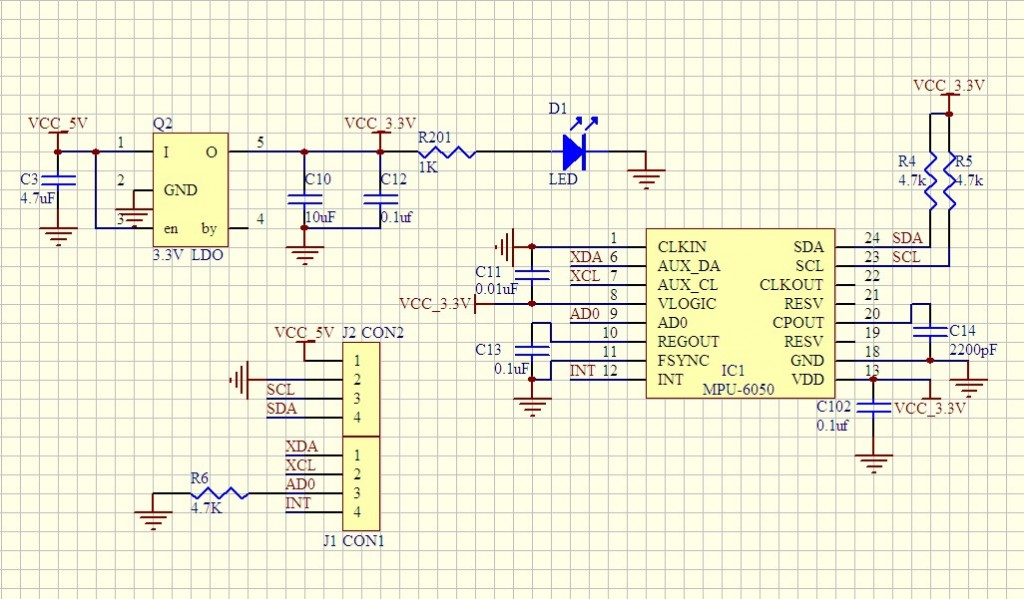
I am making my own PCB and I have been using a schematic that I found online to incorporate the MPU 6050. In the schematic, the AD0 pin is connected to the header which is pulled down to GND. If I apply 3.3v to the AD0 pin will the address change to 0x69 or will it remain as 0x68 (Connected to GND) because of the pull down resistor?

Thanks

Nice pic. Are you using Altium?

Anyway, this is direct from the MPU6050 register map:

The I2C address of the
MPU-6500 is 0x68 or 0x69 depending upon the value driven on AD0 pin.

BUT, I think AD0 needs 5V to be "driven high", but I'm not 100% sure about that. Why not buy a couple and experiment with them?

AD0 seems to be only needed if you are using two MPUs with a single Arduino: link