MPU6050 freezes

i have combined mpu6050 , arduino uno,nrf24 and l298n for a self balancing bot.
I have done the following when the sensor values were freezing :
Changed the pull up resistor(on SCL and SDA line) value to 2.2k and also 10k ( it was originally 4.7k)
added decoupling capacitor to nrf24, 7805 voltage regulator and battery terminals and ceramic caps to motor terminals
added timeout to code in arduino ide in setup( for mpu6050)

{#if I2CDEV_IMPLEMENTATION == I2CDEV_ARDUINO_WIRE
        Wire.begin();
        Wire.setClock(400000); // 400kHz I2C clock. Comment this line if having compilation difficulties
        Wire.setWireTimeout(3000, true); //timeout value in uSec
    #elif I2CDEV_IMPLEMENTATION == I2CDEV_BUILTIN_FASTWIRE
        Fastwire::setup(400, true);
    #endif}

Still the mpu freezes. kindly find the pcb layout attached,
In the end I removed the mpu ic from the board and tried using the module available in market by connecting to the jumper wires to the pcb board, still the same problem.
The mpu fives erratic value as soon as the motors are connected , without the motors connected the serial monitor gives correct values
If i limit the pid output to -90,+90, it works but motor moves slowly, increasing it to -255,+255 freezes the mpu as soon as the motor starts

I tried connecting the uno, l298n and mpu module available in market through jumper wire using the same code. It works perfectly. Is there a problem using all these on the same PCB board.
How could I resolve this, still a beginner in this. Please help


Hi, @mayankgangwani

What is your power supply?
Where are you getting the 3V3 supply?
If it is from the CH340G, pin 4 is not a 3V3 supply, it is a reference pin that has a capacitor connected to it.
It cannot supply anywhere near the current needed for the NRF and the MPU.

Do you have a DMM?
If so measure the 3V3 line while your project is running.

Did you breadboard your project and get it running before going to PCB?

Tom... :smiley: :+1: :coffee: :australia:

my power supply is 18650 li-ion battery 3.7v, 1200mah(3cells)
the 3.3v power is from CH340, It works fine if i do not connect the motors, i have monitored through serial monitor for hours the mpu as well as nrf works fine.(i have read the angles and also the nrf inspection code which is working fine) . I have also used V3 pin for powering nrf in another project which works fine
I have measured the 3.3v through dmm, that line is fine .

i have used readily available modules before going to PCB, and it all worked perfectly

Hi,
Then it can be component layout.
You have the MPU and the 298 close to each other and motor current is possibly causing noise on the MPU connections.

It would have been better to place the MPU on the other side of the controller IC and a ground plane added like around the voltage regulator.

Tom.. :smiley: :+1: :coffee: :australia:

plugging out mpu ic and connecting the mpu6050 module through jumper wire is also showing the same problem. Is changing the PCB design is the only solution, is there any way that I can be sure that the pcb design is the only problem ?

Would this design work ?? The J9 is for mpu6050 module. Rest everything is the same

Hi,
Just a thought out of right field.
You are using 4K7 for the I2C pullups, as you are using 3V3 on the pullups but then I2C bussing to a 328 which is 5V.
Might be a problem there.
You could possibly use lower resistance pullups because of the 3V3 supply.

This may help;
Look at the Response from Technical Support: reply.

Apart from the motor you have the NRF popping out RF.

Tom.. :smiley: :+1: :coffee: :australia:

I2C only has weak pull ups for the simple reason that it is pulling an input pin high.

As for the rest, the output from the NRF may be too low to trigger the gate and decreasing the pullup value will make it worse, by tying the line harder to +5V.

Test remedy, increase the pullup resistor, or simply remove it, given that if this is the I2C variant of the NRF, , the board may already have weak pull_ups.
Lower the I2C speed, to prevent the data being scrambled.

However from the photo of the board, I can only see the NRF24L01 which is an SPI device.
I thought you needed a SPI to I2C board to make this I2C?
If not, can you point me to the NRF device which has I2C as an output?

Both schematic and PCB layouts need to be looked at carefully but there are some redundant components at first glance C26, not needed.

As you said, pin 4 is a power supply line for the output stages of the CH340G and should not be used as a power line to other devices. It is most likely getting its 3V3 from the 5V supply, however I have no idea why it is being used for the NRF device, which has a VCC of 5V

Weak pullups mean a high circuit impedance when the I2C wires are HIGH.
Try lower to decrease the circuit impedance and reduce the influence of noise.

Tom.. :smiley: :+1: :coffee: :australia:

Try reading the original Phillips I2C specification.

Decreasing the pullup ties the line harder against the supply Voltage and causes slewing of the signal especially at higher data rates.

I have no idea where you get the idea it has anything to do with circuit impedance, other than in an adverse way, by decreasing the resistor value.

update: I am using the following setup to make changes easily and check , arduino , nrf24L01 , mpu6050, l298n motor driver, 25ga motor 200rpm 12v , jumper wires

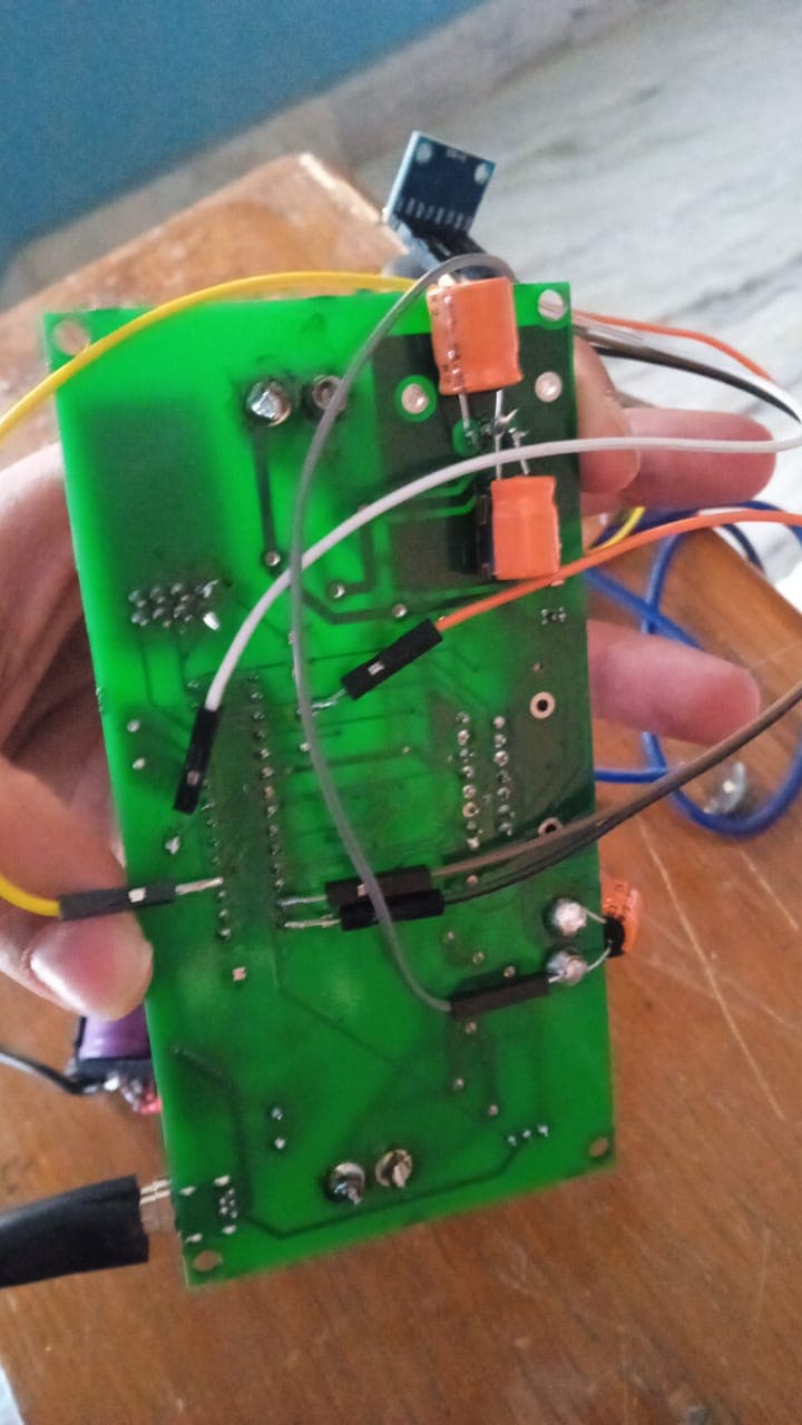
so now the pull up resisitor on mpu 6050 module is 2.2k to 3.3v, it still freezes(it takes more time to freeze than in pcb but it does) , could you please suggest what should be my next step , reducing clock speed makes the mpu6050 not functional

#include <Wire.h>

/********** PID **********/

#include <PID_v1.h>
#include <Servo.h>
#define INTERRUPT_PIN_2
double kP = 17.388;
double kI = 35;
double kD = 1;

double setpoint, input, output;   // PID variables
PID pid(&input, &output, &setpoint, kP, kI, kD, DIRECT); // PID setup

/********** radio **********/
#include <nRF24L01.h>
#include <SPI.h>
#include <RF24.h>
#include <nRF24L01.h>

RF24 radio(9, 10);    // CE, CSN
const byte address[6] = "00001";
float angleV = 0, turnV = 0;int servo = 0; // values from remote
float controlValues[3]; // array to receive both data values

/********** L298N **********/
#include <L298N.h>

// Pin definition
const unsigned int EN_A = 6;
const unsigned int IN1_A = 4;
const unsigned int IN2_A = A2;

const unsigned int IN1_B = 7;
const unsigned int IN2_B = 8;
const unsigned int EN_B = 3;

// Create motor instances
L298N rightMotor(EN_A, IN1_A, IN2_A);
L298N leftMotor(EN_B, IN1_B, IN2_B);

// motor speeds
int speedLeft = 0;
int speedRight = 0;

/********** MPU **********/
#include "I2Cdev.h"
#include "MPU6050_6Axis_MotionApps20.h"


// class default I2C address is 0x68
// specific I2C addresses may be passed as a parameter here
// AD0 low = 0x68 (default for SparkFun breakout and InvenSense evaluation board)
//AD0 high = 0x69;

MPU6050 mpu;
//MPU6050 mpu(0x69); // <-- use for AD0 high

#define LED_PIN 13 // (Arduino is 13, Teensy is 11, Teensy++ is 6)
bool blinkState = false;

// MPU control/status vars
bool dmpReady = false;  // set true if DMP init was successful
uint8_t mpuIntStatus;   // holds actual interrupt status byte from MPU
uint8_t devStatus;      // return status after each device operation (0 = success, !0 = error)
uint16_t packetSize;    // expected DMP packet size (default is 42 bytes)
uint16_t fifoCount;     // count of all bytes currently in FIFO
uint8_t fifoBuffer[64]; // FIFO storage buffer

// orientation/motion vars
Quaternion q;           // [w, x, y, z]         quaternion container
VectorInt16 aa;         // [x, y, z]            accel sensor measurements
VectorInt16 aaReal;     // [x, y, z]            gravity-free accel sensor measurements
VectorInt16 aaWorld;    // [x, y, z]            world-frame accel sensor measurements
VectorFloat gravity;    // [x, y, z]            gravity vector
float euler[3];         // [psi, theta, phi]    Euler angle container
float ypr[3];           // [yaw, pitch, roll]   yaw/pitch/roll container and gravity vector

float pitch;
long velocity;

float trimPot;
float trimAngle;

int IMUdataReady = 0;
volatile bool mpuInterrupt = false;
int servoPin = 5;
Servo Servo1;
// IMU interrupt service routine

void dmpDataReady() {
     IMUdataReady = 1;
}        


// function that actually read the angle when the flag is set by the ISR

void readAngles()  {

    mpuIntStatus = mpu.getIntStatus();
    fifoCount = mpu.getFIFOCount();
    
    if ((mpuIntStatus & 0x10) || fifoCount == 1024) {
        // reset so we can continue cleanly
        mpu.resetFIFO();
        Serial.println(F("FIFO overflow!"));
     } 
     
     else if (mpuIntStatus & 0x02) {
        // wait for correct available data length, should be a VERY short wait
        while (fifoCount < packetSize) fifoCount = mpu.getFIFOCount();

        // read a packet from FIFO
        mpu.getFIFOBytes(fifoBuffer, packetSize);
        
        // track FIFO count here in case there is > 1 packet available
        // (this lets us immediately read more without waiting for an interrupt)
        fifoCount -= packetSize;

        mpu.dmpGetQuaternion(&q, fifoBuffer);
        mpu.dmpGetGravity(&gravity, &q);
        mpu.dmpGetYawPitchRoll(ypr, &q, &gravity);

        IMUdataReady = 0;
        //count = count + 1;
    }

}
/********** SETUP **********/
void setup() {
   // 
  
     #if I2CDEV_IMPLEMENTATION == I2CDEV_ARDUINO_WIRE
        Wire.begin();
        Wire.setClock(400000); // 400kHz I2C clock. Comment this line if having compilation difficulties
        Wire.setWireTimeout(3000, true); //timeout value in uSec
    #elif I2CDEV_IMPLEMENTATION == I2CDEV_BUILTIN_FASTWIRE
        Fastwire::setup(400, true);
    #endif

    Serial.begin(115200);

    // initialize device
    mpu.initialize();
    devStatus = mpu.dmpInitialize();

    // supply your own gyro offsets here, scaled for min sensitivity
    mpu.setXGyroOffset(54);
    mpu.setYGyroOffset(-45);
    mpu.setZGyroOffset(10);
    mpu.setZAccelOffset(681); // 1688 factory default for my test chip
 
    // make sure it worked (returns 0 if so)
    if (devStatus == 0) {
        // turn on the DMP, now that it's ready
        mpu.setDMPEnabled(true);

        // enable Arduino interrupt detection
        attachInterrupt(0, dmpDataReady, RISING);
        mpuIntStatus = mpu.getIntStatus();

        // get expected DMP packet size for later comparison
        packetSize = mpu.dmpGetFIFOPacketSize();
    } else {
        // ERROR!
        // 1 = initial memory load failed
        // 2 = DMP configuration updates failed
        // (if it's going to break, usually the code will be 1)
        Serial.print(F("DMP Initialization failed (code "));
        Serial.print(devStatus);
        Serial.println(F(")"));
    }
    
    pid.SetMode(AUTOMATIC);
    pid.SetOutputLimits(-255,255);
    pid.SetSampleTime(10);
    
    pinMode(LED_PIN, OUTPUT);
    Servo1.attach(servoPin);
    radio.begin();
    radio.openReadingPipe(0, address);
    radio.setPALevel(RF24_PA_MIN);
    radio.startListening();
}

void loop() {

  // only read remote data if remote is available, otherwise balance normally
 
  if (radio.available()) {
    radio.read(&controlValues, sizeof(controlValues)); // read values of array
    
    angleV = controlValues[0]; // assign array values to control variables
    turnV = controlValues[1];
    servo = controlValues[2];
  } 
  if(servo == 1)
  {
    Servo1.write(180);
  }
  else
  {
    Servo1.write(0);
  }
  trimPot = analogRead(A3)*-1; // read dial on robot and *-1 for direction

  trimAngle = (trimPot/100) + 5 + angleV; // adjust to degrees

  if (IMUdataReady == 1) {
    readAngles();
  }

  pitch = (ypr[1] * 180/M_PI); // adjust to degrees

  if (abs(turnV) < 15) { // turnV threshold
    turnV = 0;
  }

  if (abs(angleV) < .17) { // angleV threshold
    angleV = 0;
  }

  // PID vars
  setpoint = trimAngle + angleV; 
  input = pitch;

  pid.Compute();

  // set motor speed with adjusted turn values
  speedLeft = output -  turnV;
  speedRight = output + turnV;
  
  if (pitch > 25 || pitch < -25) { // angle threshold
    leftMotor.setSpeed(0);
    rightMotor.setSpeed(0); 
  } else {
    leftMotor.setSpeed(abs(speedLeft));
    rightMotor.setSpeed(abs(speedRight));
  }

  // move motors
  if (speedLeft < 0) { 
    leftMotor.forward();
  } else {
    leftMotor.backward();
  }
  
  if (speedRight < 0) { 
    rightMotor.forward();
  } else {
    rightMotor.backward();
  }
  
  // print some control info
  Serial.print("pitch: ");
  Serial.print(pitch);
  Serial.print(" , trimPot: ");
  Serial.print(trimPot);
  Serial.print(" , angleV: ");
  Serial.print(angleV);
  Serial.print(" , turnV: ");
  Serial.print(turnV);
  Serial.print("\n");
 

}

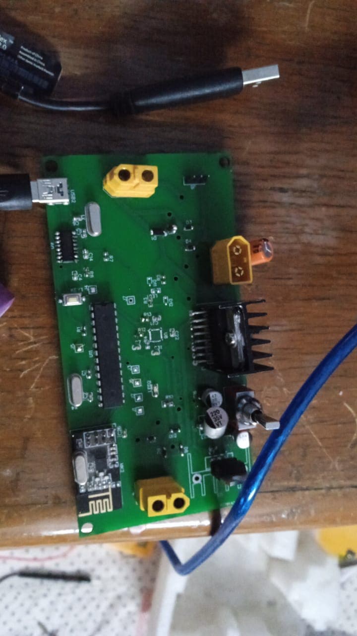
This is the complete code, i have tried replacing the 4.7k resisotor to 2.2 in my pcb still it freezed, also after removing the mpu6050 ic rom pcb tried connecting the mpu module through jumper wire it still freezed. Could you please suggest my next step to resolve this

Something like this may help 24MHz 8 Channel USB Logic Analyzer 8 CH Logic Analyzer for MCU ARM FPGA UK | eBay

It will give you an insight into what is happening with the bus.

It is strange that the reduction in speed should hang the Arduino, so I would have to presume there is something else going on.

You can disconnect the NRF board for the time being to see if the circuit stays stable, but I would suggest adding a switching regulator(D24V3F3) to power the NRF and the 6050 boards. Using the divided 3V line from the CH340G may become a problem at some point and may introduce instability with the respective boards. It may even blow the 340G given that line is not an output, but a 3V3 input for the 340G

The I2C resistors look like they are set to low values so that the lines are pulled tightly to the 3V3 line, although higher value resistors would not change this and may even help with data rates.

I see a novel approach with the SPI clock to the NRF, using a LED and series resistor to reduce the Voltage from 5V. Its also a good indicator for showing there is data being transmitted. Although you do need to check this Voltage is correct.

as i have posted in my latest post, the nrf now is connected to 3.3v of arduino uno, which is through onboard voltage regulator i guess, i disconnected the nrf and tried ,its still freezes. I have noticed it shows this behaviour only when motors are connected.
and also i have made another pcb in which i have powered nrf from 340g and it works fine but in that project the mpu has no role so i am confused that what is the actual problem, also in arduino nano clone (ch340) , the 3.3v pin is directly connected to 340g which supplies 3.3v to that particular pin.
In latest post the mpu is everything is powered through l298n 's 5v , which i eventually intend to do because why use multiple regulators, only the nrf is connected to 3.3v of arduino uno pin .

Would using any kind of capacitor help ?? there are already 220 capacitor on l298n onboard so i didnt feel the need to connect any more . Also would inductors also help ?

OK possibly my fault given I thought you had said the NRF was on the I2C bus, whereas it is on a SPI bus which goes to separate pins of the Arduino.
I do believe the Arduino 3V3 can supply up to 150mA, which is ample for that device. however the 340G is a Vcc input, so may be internal working 3V3 where the 5V is on a divider chain to drop this down to 3V3. What the current output is, I just don't know. I would hazard a guess and say this divider chain device would blow if the 340G current + whatever is hanging on the 3V3 became too much. bye bye 340G

The freezing you are getting is clearly from the I2C bus, which could mean it is hanging because the pulse stretching timeout is not working.
I will have to look through the code, but would assume you have not specified weak pullups on the inputs to the Arduino.

Could you please post the full code, including the .h files you have created plus where you got any other libraries.

The ST data sheet does state the following
ST Data Sheet
Vs Supply Voltage for the Power Output Stages.
A non-inductive 100nF capacitor must be connected between this
pin and ground.

Vss Supply Voltage for the Logic Blocks. A100nF capacitor must be
connected between this pin and ground.

As normal all supply lines should be decoupled close to the device

Inductors won't help, although I did notice on the data sheet is specifies fast diodes to be used, whereas you have 1N4007, which are rectifier diodes(slow). Although in all honesty I don't think these will stop it from working.

I have posted the complete code in the last post
update : i have attatched capacitors like this to reduce electric noise , and it worked like a charm in the latest setup ( everything connected through jumpers)


this is according to the pololu article : Pololu - 9. Dealing with Motor Noise.

then i connected the mpu6050 module to my pcb through jumper wires, as i plugged out the MPU IC on pcb to check.


Now here the output marked in green worked perfectly without any problem, but as soon as connected the motor to output marked in red (output 1 and 2) , it again disrupted the functioning . According to me this problem is not due to I2C lines but electrical noise since adding caps solved it in earlier setup. So i commented the nrf lines in code and then tried it still hanged in the red marked output. I then doubled down the caps at the motor

and also added 220uf 40v caps to 7805 regulator even though there are 47uF caps already in place, and also 100uF cap to battery

still the problem is same in pcb, Is it due to ground plane being close to that output?? or something else, I would be grateful if anybody could help

You said the arduino was hanging, help can only be given with accurate diagnostics.

The PCB layout is a complete mess anyhow, but you do need to check the junction of D9 and D10 are at Gnd. From what I can make out this line is just dangling with a string of components which are supposed to be at Gnd.

Putting a load of capacitors across your motor, instead of a single capacitor is not really going to help. Think of it as placing a short circuit at higher frequencies, the frequency is determined by the value of the capacitor.

Decoupling capacitors on IC's, are supposed to be connected as close to the pins of the IC as possible, otherwise they won't be as effective.

You appear to think that jamming a load of capacitors around the place is some sort of solution.
The 220uF capacitors around the 7805 are not needed as 47uF should suffice.
Large capacitors are usually added to smooth out any ripple you have on the PSU lines. In this case you are running this off a DC battery source(No ripple).

This topic was automatically closed 180 days after the last reply. New replies are no longer allowed.