Multi-plexing "flickering" problem using a dual 74HC595 setup

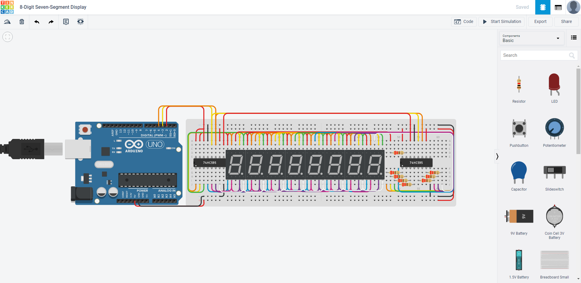
Hello. Over the last few days, I have been writing a program for a 8-digit 7-segment driven by a dual 74hc595 setup that I designed in tinkercad while attending my career technical center. The link for the project will be at the end of this post if you want a visualization of the hardware. The problem that I initially had was displaying 8 characters at a time using a for() loop that displayed the same character on every "digit" of the display. Now, despite having multiplexed the entire display with two nested for loops, iterating each individual segment through each individual digit without having any problems, when taking the "draw the whole letter then go to the next digit" approach, the display began to flicker. I figured as maybe the dual-shift register setup didnt have enough power to flicker through all 8 digits 8 segments at a time, that the solution would be to do what I originally did but only display segments if they should be displayed. However, the same flickering issue reoccurred, even though I was only displaying the segments of a single digit. I tried this program on both an Arduino Uno and and Arduino Mega with similar flickering affects. I'm hoping someone can tell me this is a simple problem with my code, and not a physical constraint of the arduino or the shift registers, as I don't have the money to buy "better" versions of either. The code seems to work in TinkerCad, so I'm stumped on this. Thanks for the help :slight_smile:

Here's my code:

// ArduinoSTL - Version: Latest

//Timer//
long startTime = millis();
long thisTime;
long elapsedTime;

//Pins//
int dataPin = 2;
int latchPin = 3;
int clockPin = 4;

int order[8] {4, 6, 8, 7, 6, 3, 2, 1};
char chars[1] {'A'};
byte cBytes[1] {B11111100};

bool debug=false;


void testSetup()
{
    
}

void testLoop()
{
  
}

void setup() 
{
  //Debug
  Serial.begin(9600);
  //Pins
  pinMode(dataPin, OUTPUT);  
  pinMode(latchPin, OUTPUT);
  pinMode(clockPin, OUTPUT);

  //"Just to be safe"
  digitalWrite(latchPin,LOW);
  digitalWrite(clockPin,LOW);

  if(debug){testSetup();}  
}

void loop() 
{
  //Timer
  thisTime=millis();

  for(int i=0; i<8; i++)
  {
    displayChar('A', 1, i);
  }
  
  if(debug){testLoop();}
  //Timer
  elapsedTime=thisTime-startTime;
}

void testOrder()
{
  for(int i=0; i<8; i++)
  {
    pushByte(255-1, true);
    pushByte(powTwo(i));
    Serial.println(powTwo(i));
    dump();
    delay(1000);
    
  }
}

byte changeOrder(byte b, int o[8])
{
  
}
void pushBit(int i)
{
  bool b = convInt(i);
  digitalWrite(clockPin, LOW);
  digitalWrite(dataPin, b);
  digitalWrite(clockPin, HIGH);
}

//Push 8 bits
void pushByte(byte B){pushByte(B, false);} //Default
void pushByte(byte B, bool msb)
{
  bool bArray[8];
  byteToArray(B, bArray);
  
  //Push bit per boolean array value
  if(!msb){
    for(int i=0;i<8;i++)
    {
      pushBit(bArray[i]);
    }
  }else if(msb)
  {
    for(int i=7;i>=0;i--)
    {
      pushBit(bArray[i]);
    }
  }
}

//PULL THE LEVER
void dump()
{
  digitalWrite(latchPin, HIGH);
  digitalWrite(latchPin, LOW);
}

//Convert 0 or 1 to true or false (not in that order LOL)
bool convInt(int i)
{
  if(i==0){return false;}
  else if(i==1){return true;}
  else{Serial.println("Error in convInt, 1 or 0 not used");}
  
  return false; 
}

//Because I can't remember
int powTwo(int i){return pow(2, i)+.5;}

//Display char segment at index(i)
void displayChar(char c, int digit){displayChar(c, digit, false, 0);} //default
void displayChar(char c, int digit, int i){displayChar(c,digit,true,i);} //Display char segment at index(i)
void displayChar(char c, int digit, bool index, int i)
{
  bool cArray[8];

  digit-=1; //Programming starts with 0, we want the user to input the digit starting with 1
  digit = powTwo(digit); // Convert digit to binary value
  digit=255-digit; //Flipped bc "anode", duh
  
  //Converts ASCII byte to "svenByte"
  for(int i=0;i<sizeof(chars)/sizeof(chars[1]);i++)
  {
    if(c==chars[i]){
      c=cBytes[i];
    }
    else if(c!=0)
    {
      c=0;
      Serial.println("displayChar byte conversion failure");
    }
  }

  //changeOrder(c)
  byteToArray(c, cArray);
  
  if(!index){
    pushByte(digit, true); //Push ground bit first
    pushByte(c);
    dump(); //PULL THE LEVER!!!
  }
  else{
    if(cArray[i]){
      pushByte(digit, true); 
      pushByte(powTwo(i));
      dump();
    }
  }
  
}

//Convert byte to boolean array
bool byteToArray(byte B, bool *bo)
{  
  for(int i=7;i>=0;i--)
  {
    int p=(powTwo(i));
    if(B>=p)
    {
      bo[i]=true;
      B-=p;
    }
    else{bo[i]=false;}
  }

  return bo;
}
bool timer(int time){
  if(elapsedTime % time == 0){return true;}
  else{return false;}
}

And here's the link to the TinkerCad setup:
Click me

(the link expires in 360-something hours, I can refresh it if necessary. Feel free to make changes, as I made a back-up of the file :slight_smile:

Also, here's a video of the flickering issue in slow motion, in case it helps
Click me

notmage:
And here's the link to the TinkerCad setup:
Click me

Unfortunately, that appears to be a private link. :astonished:

I fear I have difficulty following your turgid code - excessively dissected into functions.

I do wonder what the point of this is? Multiplexing in this fashion can only be considered a - rather tedious - exercise with no practical value - other than to remind you to think through your code carefully. :grinning:

If you actually want to use a 7-segment display, these are most certainly not expensive (US$2.50 posted) and do the job properly with a minimum component count, require only three control pins to update and can be easily chained.

You did not publish your circuit schematic. Did you include the resistors?

// ArduinoSTL - Version: Latest

So in what way is this helpful to you? Does this line magically change when you save another version of the code?

not a physical constraint of the arduino or the shift registers,

What ever your problem it is not this.

Our problem is we don’t know how you have wired things up.
Your problem is that given the thing is wired up correctly your code is a long way off even beginning to do anything approaching what you want to do.

Does your display take ASCII? Can you post a link to it please.

Also please read the how to use this forum sticky post, it will tell you what information to provide when asking a question.

Are you using current limiting resistors on the display segments ?
It is not clear from the video and your wiring diagram is not visible.

I apologize, it appears you need to have a tinkercad account in order to view my link. Below will include a .brd file (as it seems to be the only file output on tinkercad) and a screenshot of the display. Yes, I'm using 220 ohm current resistors to the ground pins, and no current resistors to the "segment" pins. I apologize if my code is confusing, I started programming with Java which is object oriented as opposed to straight forward code. The general idea of the flow of the program is as follows:

displayWord(String s)
{ 
 for(each char in s) //multiplexes from digit 1-8
 {
   if (char should be displayed)
   {
     convertChar(); //converts c from ascii to parallel output
     displayChar();
   }
 }
}
displayChar()
{
 for(each segment per digit) //Multiplexes each segment per digit
 {
   if(segment should be displayed)
   {
     displaySegment(i);
   }
 }
}

As goes this line of code:

// ArduinoSTL - Version: Latest

I did not put it in myself. It was auto-generated by one of the Arduino libraries I was using prior to starting this project. To answer

I do wonder what the point of this is? Multiplexing in this fashion can only be considered a - rather tedious - exercise with no practical value

, the power limitations of the

dual 74hc595 setup

requires me to be creative and multiplex to limit the maximum current output of said devices. And finally, as goes the comment

If you actually want to use a 7-segment display, these are most certainly not expensive (US$2.50 posted) and do the job properly

, A.) everything is expensive when you have 0 dollars. And B.) the whole purpose of micocontroller programming is to do it yourself, and not have others do it for you. This is the first and only time I'll ever ask for help on a forum regarding this kind of stuff, because this is the first time I've ever been stumped. The problem isn't likely to be hardware related, as I

multiplexed the entire display with two nested for loops, iterating each individual segment through each individual digit without having any problems

. Hopefully the addition of this information will be sufficient to find the root of this problem. Thank you for your time.

8 digit seven segment display brd .zip (19.1 KB)

Hopefully the addition of this information will be sufficient to find the root of this problem.

Well you were asked for a schematic and a link to that display, nether of which you have supplied, so no, still not sufficient information.

What you have supplied is a physical layout diagram who's only use is to blindly layout the components on a solder-less bread board. To an engineer that sort of thing is impossible to determine what the design is, nor if you have made any mistakes.

A .brd file is useless unless you have Tinker CAD which rules out most members here.

convertChar(); //converts c from ascii to parallel output

The comment makes no sense unless the display can handle an ASCII input. That is a very unusual thing for a display to be able to do. You can get displays that do this but normally the ones that can do this do not require multiplexing. This part of your code for the first post:-

//Converts ASCII byte to "svenByte"
  for(int i=0;i<sizeof(chars)/sizeof(chars[1]);i++)
  {
    if(c==chars[i]){
      c=cBytes[i];
    }
    else if(c!=0)
    {
      c=0;
      Serial.println("displayChar byte conversion failure");
    }
  }

Does not convert from ASCII to a seven segment representation of the ASCII, which is what I suspect that you need.

The problem isn't likely to be hardware related,

It is if your display is not operating in the way that Tinker CAD is emulating the display.

So I hope you can see that we need a link to the display you are using, and a schematic to see what circuit you actually are working to.

The multiplexing strategy is not very transparent from the fritzing diagram.
With only 3 arduino pins in use, one shift register must handle the common pins and one must handle the segment pins. The shift register which handles the segment pins should have the current limiting resistors (well, that would be usual for optimum brightness but there are other strategies). The shift register that handles the common pins should have only 1 connection to each of the 8 displays. You appear to have arbitrarily assigned half the pins of each display to 1 shift register and the other half to the other shift register. You appear also not to have considered the maximum current rating of the shift register pins. The shift register which drives the common pins must, at any given moment, power up to 8 segments (including the decimal point).

Are the displays common anode or common cathode ? what is the pinout and segment current rating ?