Hey, I´m working on a project where I need more Buttons then I have interrupt Pins available.
I don´t want to use digitalRead() in the loop and poll every button every loop, it slows down the loop to much for my application.
I was thinking of hooking up the Buttons individually to normal IO pins and also wire them together into a single Interrupt Pin. (INPUT_PULLUP in IO and Interrupt pin)
When a button is pressed, the interrupt routine triggers and reads the normal IO pins with digitalRead to find out which one´s been pressed. I´m using diodes between the buttons and the interrupt Pin to ensure only the reading for the pressed button changes.
It´s working so far as only the reading of the button I pressed ever changes. Sometimes I get the reading of "1" on the pressed button though. The ISR is executed like 6 times for every button press (don´t seem to be the best buttons).
I´ve tried to debounce them with delay() but delay doesnt seem to have any effect in an ISR.
I´m using millis() now to debounce for 200ms and the ISR only triggers once now for every button press. In 10-20% of button presses I still get a "1" reading from the pushed button though making it impossible to figure out which button has been pressed.
Any ideas?
Thanks
int button1=5;
int button2=4;
int volatile buttonState1;
int volatile buttonState2;


void setup() {
  // put your setup code here, to run once:
Serial.begin(9600);
pinMode(button1,INPUT_PULLUP);
pinMode(button2,INPUT_PULLUP);
pinMode(2,INPUT_PULLUP);

attachInterrupt(0,test,FALLING);
}

void loop() {

}

void test(){
  static unsigned long last_interrupt_time = 0;
  unsigned long interrupt_time = millis();
  if (interrupt_time - last_interrupt_time > 200) {
    buttonState1=digitalRead(button1);
    buttonState2=digitalRead(button2);
    Serial.print(buttonState1);
    Serial.println(buttonState2);
  }
  last_interrupt_time = interrupt_time;
}
What are you trying to do that requires interrupts to detect button presses? The normal way is just to use digitalRead() and then it does not matter what pins you use.
b. It's just a theory but, you could set a flag in the ISR which enables a function in loop() which does the debouncing and switch determination. The function would present its results then self-disable by resetting the ISR flag.
You should not ever need interrupts for buttons pressed by humans. If it's an encoder on a shaft or conveyor belt, then maybe.
I would fix the problems in loop() - which you didn't show - before using interrupts.
If you absolutely must have interrupts then look into the pin-change interrupts. All pins can be used as interrupts but they aren't as simple as the native interrupts on pin 2 and 3.
You might want to look into the PinChange interrupts. It seems like the perfect software solution to your problem. Specifically, several pins are assigned to one interrupt. You get one interrupt any time any of those pins rise or fall, and you have to then check the pins and figure out which one changed. This looks an awful lot like what you're trying to do with hardware. Plus, there are more than 2 of them.
Another possibility would be to just use the PINx pseudo variables to check your pins. This can be done way faster than any interrupt, so your concern about slowing down the loop might be avoided. Also, you can check multiple pins at once if they're on the same port.
Pins 4 and 5 are PD4 and PD5, which is bits 4 and 5 on Port D.
void loop() {
  if ((PIND & 0x30) != 0x30) {    // Is either button pressed?
    if ((PIND & 0x10) == 0) {
        // Pin4 is LOW
    }
    if ((PIND & 0x20) == 0) {
        // Pin5 is LOW
    }
  }
}
The normal case (when none of the buttons are pressed) takes 5 clock cycles.
I´ve built an inverted Pendulum out of an old inkjet printer (not the basic balancing robot).
It´s using two PID controllers "in series" running at a 2ms sample time. So one loop cant take longer than 2ms or the PID math gets thrown off. The pendulum is working fine, I just want it to make it a little bit more presentable with start stop buttons, different modes etc.
I know I´m already close to the 2ms because I cant´use a single Serial Output in the loop.
A single serial Output , in an otherwise identical code, throws the behaviour of the whole system completely off.
Thats why I want to avoid pulling the buttons every pin in the loop.
I´ll look into PinChage Interrupts and Port Manipulations tomorrow.
Two milliseconds? I don't think your digitalRead() is the problem. It takes about 3.5 microseconds to do a digitalRead(). And it takes about a quarter of a microsecond to check the input port.
Serial output, on the other hand, is quite slow. at 9600 baud, that's about 1 ms per character. You might try bumping your baud rate up to 115200. That might help.
The other thing you might try is not doing a serial output on every loop. If you don't fill the buffer, it doesn't block. If you can consolidate your data and only send to serial every 100 loops or so, it should be able to keep up.
Ok, sorry. Seems I wasnt aware of how quick digitalRead really is (or how slow SerialOutput for that matter).
There´s really not much to improve on the code I think. The whole PID calculations are done by the PID library and all my code is pretty much some if´s for driving the motor in different directions.
Once i figured out that the Serial output was my problem I abandoned it, it´s not really necessary anyway, it was just nice to have for debugging. I thought about not using the Serial output every loop and bundle all the output as one package and not have Serial.print for every value but havent come around to do it yet.
Seems like I shoudnt have a problem at all connecting the buttons to normal IO pins. Thanks
On the other hand, now I just want know know whats wrong with my initial idea and why I get false readings from time to time. Not that my idea is the "right way" but I think it could be quite usefull if it would work.
Think laterally here. Have you tried increasing the PID sample time? Changing it from 2 to 3 ms shouldn't affect stability. The extra millisecond is basically an extra eternity for checking external buttons and doing some conditional logic.
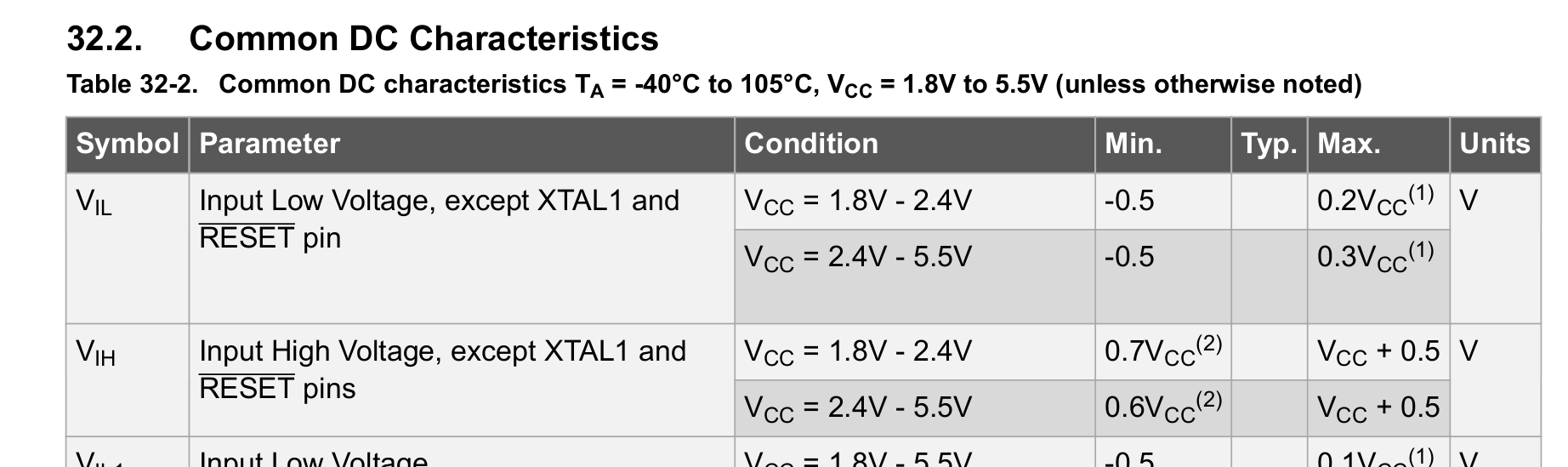
According to the spec sheet, the input voltage threshold between HIGH and LOW is somewhere between 0.3 and 0.7 volts. If your diode has a voltage drop of 0.7 volts, that's right in the grey area, and could conceivably go either way.
I think there's a way to use a MOSFET as a diode with a lower voltage drop. Maybe try that.
Or use the switches high side instead of low side and use pull-down resistors and run the switch to VCC instead of ground. And invert the logic in the sketch.
The PID library calculation is very slow because it uses floating point maths. I made a version with integer maths that takes about 100µsecs to compute and I know that was a lot faster - but I can't immediately find my timings for the official PID library.
I have come across this discussion trying to solve very same problem myself. I just don't want to be reading buttons in a loop. It's just ugly for a full-size computer programmer that I am (I realize that it may be different with microcontrollers, but... habits). And... after reading this discussion... I think that it may be worth trying with OR logical gates? So... instead of using diodes, I would connect all the buttons to multi-input OR logical gate and output of this gate to Arduino interrupt pin. What do You think?
I think that an array of input pins and a for loop to read them is a neat and tidy solution if you need to determine which button has been pressed. If you can arrange for all of the inputs to be on the same port then reading the port directly is an even neater solution.
A port expanser like the pcf8574 has an interrupt output which is asserted when an input changes.
So the ISR can then interrogate the chip and find out which input has changed.